
STANLEY CM150-08
PHI Precision CM150-08 Control Module User Manual
Electric Latch Retraction Control Module
1. Introducció
This user manual provides detailed instructions for the installation, operation, and maintenance of the STANLEY PHI Precision CM150-08 Control Module. This module is designed for electric latch retraction systems, offering precise control and integration capabilities.
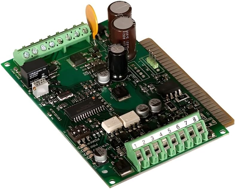
Figure 1: The PHI Precision CM150-08 Control Module, a green circuit board with various electronic components, connectors, and a gold-colored edge connector.
2. Especificacions
The CM150-08 control module features user-selectable delay settings and integrates fire alarm interruption capabilities. Key specifications are detailed below:
- Entrada Voltage: 5-24 VDC or VAC
- Corrent d'entrada: Aproximadament 0.005 Amp
- Amplada mínima del pols: 0.25 segons
- Current Pulse: 4.75 Amp (2 segons màxim)
- Corrent continu: 3.6 VDC / 0.8 Amp
- User Selectable Delay: 0-4 minutes after input is removed
- Fire Alarm Terminal: Red LED (D3) blinks when fire alarm interrupts circuit. Provides immediate termination of output. Accepts normally closed contacts or 5-24 Volts from a listed fire detecting device.
- Relay Isolated Contacts: Provided for remote signaling (e.g., door operator). Normally open or normally closed contacts rated at 0.5 Amp, 24VDC or VAC.
- Operació de contacte: Follows successful operation of the ELR device.
- Pes aproximat: 1 kg (0.45 lliures)
- Dimensions: Aproximadament 5.24 x 3.7 x 2.99 polzades (13.3 x 9.4 x 7.6 cm)
3. Configuració i instal·lació
Proper installation is crucial for the optimal performance of the CM150-08 module. Ensure all power sources are disconnected before beginning installation.
3.1 Connexions de cablejat
The module features multiple terminals for various connections. Refer to the diagram below for typical wiring configurations.
Figure 2: Detail of the CM150-08 module showing the green terminal blocks labeled 1 through 8, used for various input and output connections.
- Entrada d'alimentació: Connect the 5-24 VDC or VAC power supply to the designated power input terminals. Observe polarity if using DC.
- ELR Device Connection: Connect the electric latch retraction device to the appropriate output terminals. Contact operation will follow successful ELR device activation.
- Entrada d'alarma d'incendi: For fire alarm integration, connect the fire detecting device (normally closed contacts or 5-24 Volts) to the Fire Alarm Terminal. This input provides immediate output termination.
- Remote Signaling: Utilize the relay isolated contacts for remote signaling applications, such as connecting to a door operator. These contacts are rated at 0.5 Amp, 24VDC or VAC.
3.2 Configuració del retard
The CM150-08 allows for a user-selectable delay of 0 to 4 minutes after the input is removed. Consult the module's internal jumpers or dip switches (if present, not explicitly detailed in product description but implied by "user selectable") for configuration. Refer to the specific wiring diagram provided with your unit for exact jumper settings.
4. Instruccions de funcionament
Once installed and wired correctly, the CM150-08 module operates automatically based on its configured settings and inputs.
- Funcionament normal: The module will activate the ELR device upon receiving the specified input signal.
- Funció de retard: If a delay is configured, the ELR device will remain active for the set duration (0-4 minutes) after the input signal is removed.
- Fire Alarm Override: In the event of a fire alarm signal, the module will immediately terminate its output, overriding any current operation or delay. The red LED (D3) will blink to indicate a fire alarm interruption.
- Remote Signaling: The isolated relay contacts will change state in conjunction with the ELR device's successful operation, providing feedback for connected remote systems.
5. Manteniment
The CM150-08 control module is designed for reliable, long-term operation with minimal maintenance. However, periodic checks are recommended to ensure continued performance.
- Inspecció visual: Periodically inspect the module and its connections for any signs of damage, loose wiring, or corrosion.
- Integritat de la connexió: Ensure all terminal connections are secure. Loose connections can lead to intermittent operation or failure.
- Condicions ambientals: Ensure the module is operating within its specified environmental conditions (temperature, humidity) to prevent premature wear.
- Neteja: Si cal, netegeu suaument el mòdul amb un drap sec i suau. No utilitzeu netejadors líquids ni dissolvents.
Nota: Do not attempt to open the sealed components of the module or perform internal repairs. Refer all complex issues to qualified service personnel.
6. Solució De Problemes
This section provides guidance for common issues encountered with the CM150-08 module. If the problem persists, contact technical support.
| Problema | Causa possible | Solució |
|---|---|---|
| Module not responding to input. | No power; incorrect wiring; faulty input signal. | Verify power supply (5-24VDC/VAC). Check all wiring connections for correctness and security. Test the input signal source. |
| ELR device not retracting. | Module output issue; ELR device malfunction; insufficient power. | Confirm module is receiving input and its output terminals are active. Check the ELR device for proper function. Ensure adequate power supply to both module and ELR. |
| Red LED (D3) blinking without fire alarm. | Faulty fire alarm input; short circuit on fire alarm terminal. | Inspect fire alarm wiring for shorts or incorrect connections. Test the fire detecting device. |
| Delay function not working as expected. | Incorrect delay setting; continuous input signal. | Review the user-selectable delay settings (jumpers/dip switches). Ensure the input signal is indeed removed for the delay to initiate. |
7. Informació de la garantia
This product is covered by a limited warranty provided by STANLEY. For specific warranty terms, duration, and conditions, please refer to the warranty card included with your product or visit the official STANLEY weblloc web. Conserveu el comprovant de compra per a reclamacions de garantia.
Nota: Unauthorized modifications or repairs will void the product warranty.
8. Atenció al client
For technical assistance, troubleshooting beyond this manual, or service inquiries, please contact STANLEY customer support.
- Weblloc: www.stanleytools.com
- Telèfon: Refer to the STANLEY weblloc per als números de contacte regionals.
When contacting support, please have your product model number (CM150-08) and purchase information ready.
Ask a question about this manual
Ask about setup, troubleshooting, compatibility, parts, safety, or missing instructions. Manuals+ will review the question and use this page’s manual context to help answer it.