
1. Introducció
The MFJ-969 is a versatile manual antenna tuner designed for amateur radio operators. It provides a wide matching range for various antennas across the 1.8 to 50 MHz frequency spectrum, handling power levels up to 300 Watts PEP SSB. This manual details the proper setup, operation, and maintenance of your MFJ-969 tuner to ensure optimal performance and longevity.
Característiques principals:
- 300 Watts PEP SSB power handling.
- Wide antenna matching range.
- Full-size, lighted Cross-Needle SWR/Wattmeter for true peak forward power readings.
- QRM-Free PreTune function for silent tuning.
- 8-position antenna switch for multiple antenna configurations.
- Built-in 50 Ohm dummy load for testing and tuning.
- Heavy-duty 4:1 balun for balanced line antennas.
- Durable aluminum case with a scratch-proof multi-colored Lexan front panel.
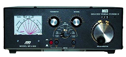
Figura 1.1: Davant view of the MFJ-969 Manual Tuner. This image displays the unit's compact design, including the large SWR/Wattmeter, tuning controls, and antenna selector switch on its multi-colored Lexan front panel.
2. Informació de seguretat
Please read and understand all safety instructions before operating the MFJ-969 tuner. Failure to do so may result in personal injury or damage to the equipment.
- Vol. Alttage: This device operates with high radio frequency (RF) voltages. Never touch antenna connections or internal components while transmitting.
- Posada a terra: Always ensure the tuner and your radio equipment are properly grounded to prevent electrical shock and minimize RF interference.
- Nivells de potència: Do not exceed the maximum power rating of 300 Watts PEP SSB. Exceeding this limit can damage the tuner and connected equipment.
- Ventilació: Ensure adequate ventilation around the tuner to prevent overheating, especially during prolonged operation at high power.
- Condicions ambientals: Operate the tuner in a dry environment, away from moisture, extreme temperatures, and direct sunlight.
- Manteniment: Demaneu totes les tasques de manteniment a personal qualificat. No intenteu obrir ni reparar la unitat vosaltres mateixos.
3. Contingut del paquet
Verifiqueu que tots els elements siguin presents al paquet:
- MFJ-969 Manual Tuner + SWR Unit
- Manual de funcionament (aquest document)
- DC Power Cable (for meter illumination)
4. Controls i indicadors
4.1 Controls del panell frontal:
- SWR/Wattmeter: Displays forward power, reflected power, and SWR. Features a lighted cross-needle design for easy reading.
- TRANSMITTER TUNING (TUNE) Knob: Adjusts the input impedance to the tuner.
- ANTENNA TUNING (LOAD) Knob: Adjusts the output impedance to the antenna.
- INDUCTANCE Switch: Selects various inductance values for matching.
- ANTENNA Switch: Selects between different antenna ports (e.g., Coax 1, Coax 2, Balanced Line, Dummy Load, Bypass).
- METER Switch: Selects meter range (e.g., 30W, 300W) and function (e.g., FWD/REF, SWR).
- LIGHT Switch: Turns the meter illumination on or off.
4.2 Rear Panel Connections:
- TRANSMITTER Input (SO-239): Connects to your transceiver's antenna output.
- COAX 1 / COAX 2 Outputs (SO-239): Connects to coaxial fed antennas.
- BALANCED LINE Terminals: Connects to balanced line antennas (e.g., ladder line, open wire).
- GROUND Terminal: Connects to a good station ground.
- Jack d'entrada de CC: For connecting the 12V DC power supply for meter illumination.
5. Configuració i connexions
Follow these steps to properly connect your MFJ-969 tuner to your amateur radio station:
- Posada a terra: Connect a heavy-gauge wire from the TERRA terminal on the rear panel of the MFJ-969 to a reliable station ground. This is crucial for safety and performance.
- Connexió del transceptor: Use a high-quality 50 Ohm coaxial cable (e.g., RG-8X, RG-213) to connect your transceiver's antenna output to the TRANSMISSOR input (SO-239) on the rear of the MFJ-969.
- Connexió d'antena:
- Antenes coaxials: Connect your coaxial-fed antenna(s) to the COAXIAL 1 or COAXIAL 2 SO-239 outputs.
- Balanced Line Antennas: Connect the two wires of your balanced line antenna to the LÍNIA EQUILIBRADA terminals.
- Alimentació de CC (opcional): If you wish to use the meter illumination, connect a 12V DC power source (not included) to the ENTRADA DC jack. Ensure correct polarity.
6. Instruccions de funcionament
This section outlines the general procedure for tuning your antenna system with the MFJ-969.
6.1 Initial Settings:
- Set your transceiver to a low power output (e.g., 5-10 Watts).
- Estableix el METTRE switch to the appropriate power range (e.g., 30W).
- Estableix el ANTENA switch to the port connected to your desired antenna.
- Enceneu el LLUM switch if meter illumination is desired and DC power is connected.
6.2 Tuning Procedure (QRM-Free PreTune):
The MFJ-969 features a QRM-Free PreTune function, allowing you to tune without transmitting a signal that could interfere with other stations.
- Estableix el ANTENA canviar a CÀRREGA FICTÍCIA posició.
- Transmit a continuous carrier (e.g., AM, FM, or CW key down) at low power.
- Ajusteu el SINTONITZACIÓ DEL TRANSMISOR i SINTONITZACIÓ DE L'ANTENA knobs for minimum SWR on the meter. The SWR should be 1:1 on the dummy load.
- Once tuned to the dummy load, switch the ANTENA switch to your desired antenna (e.g., COAXIAL 1).
- Momentarily transmit a low-power carrier. Adjust the SINTONITZACIÓ DEL TRANSMISOR i SINTONITZACIÓ DE L'ANTENA knobs for the lowest possible SWR. Aim for 1.5:1 or lower.
- Once a satisfactory SWR is achieved, you can increase your transceiver's power output, ensuring the SWR remains low.
6.3 Using the SWR/Wattmeter:
The cross-needle meter simultaneously displays forward power, reflected power, and SWR. The point where the two needles cross indicates the SWR. The left needle indicates forward power, and the right needle indicates reflected power.
- Select the appropriate power range (30W or 300W) using the METTRE interruptor.
- For accurate SWR readings, ensure the tuner is properly matched to the antenna.
6.4 Using the Dummy Load:
The built-in 50 Ohm dummy load is useful for testing your transceiver, setting power levels, and performing the QRM-Free PreTune without radiating a signal.
- Estableix el ANTENA canviar a CÀRREGA FICTÍCIA.
- Transmit at your desired power level. The SWR should read 1:1, and the forward power should match your transceiver's output.
- Avoid prolonged transmission at high power into the dummy load to prevent overheating.
7. Manteniment
The MFJ-969 tuner is designed for reliable operation with minimal maintenance.
- Neteja: Keep the unit clean and free of dust. Use a soft, dry cloth to wipe the exterior. Do not use abrasive cleaners or solvents.
- Connexions: Periodically check all coaxial and ground connections to ensure they are secure and free from corrosion.
- Emmagatzematge: If storing the unit for an extended period, disconnect all cables and store it in a dry, temperature-controlled environment.
8. Solució De Problemes
If you encounter issues with your MFJ-969 tuner, refer to the following common problems and solutions:
| Problema | Causa possible | Solució |
|---|---|---|
| High SWR cannot be tuned out. | Antenna mismatch too severe; incorrect antenna selection; faulty antenna or feedline. | Check antenna and feedline for damage. Ensure correct antenna port is selected. Some antennas may be too far out of resonance for the tuner's range. |
| Meter lights do not illuminate. | No 12V DC power connected; LIGHT switch off; faulty DC cable. | Ensure 12V DC power is connected and the LIGHT switch is on. Check DC cable for continuity. |
| SWR reading is erratic or unstable. | Poor ground connection; loose coaxial connectors; RF feedback. | Verify all ground connections are secure. Tighten all coaxial connectors. Ensure proper RF choking on feedlines if necessary. |
| No power reading on meter. | Transceiver not transmitting; METER switch set to incorrect range; faulty coaxial cable. | Confirm transceiver is transmitting. Select appropriate power range on METER switch. Test coaxial cables. |
9. Especificacions
| Número de model | MFJ969 |
| Interval de freqüència | 1.8 - 50 MHz |
| Manipulació de potència | 300 Watts PEP SSB |
| Impedància | 50 ohms (nominal) |
| Connexions d'antena | 2 x SO-239 (Coaxial), Balanced Line Terminals |
| Connexió del transceptor | 1 x SO-239 |
| Càrrega simulada | Built-in 50 Ohm |
| Balun | Heavy-duty 4:1 |
| Il·luminació del comptador | Requires 12V DC (external power supply not included) |
| Dimensions del producte (H x P x A) | 3.5" x 10.5" x 9.5" (aproximadament) |
| Pes de l'article | 6.34 lliures (aproximadament) |
10. Garantia i Suport
MFJ products typically come with a manufacturer's warranty. For specific warranty terms, duration, and service procedures, please refer to the warranty card included with your product or visit the official MFJ Enterprises, Inc. website. For technical support or repair inquiries, contact MFJ customer service directly. Keep your purchase receipt as proof of purchase for warranty claims.
Note: Warranty and support policies are subject to change by the manufacturer. Always consult the most current information provided by MFJ.