Introducció
The UNI-T UT151C is a high-reliability handheld digital multimeter designed for precise electrical measurements. It functions as a multimeter, LCR meter, and temperature tester, capable of measuring DC/AC voltage, DC/AC current, resistance, capacitance, and temperature. This manual provides essential information for the safe and effective operation, setup, and maintenance of your UT151C device.
Informació de seguretat
Avís: To avoid electric shock or personal injury, read all safety information before using this product. Use the product only as specified in this manual, or the protection provided by the product may be impaired.
- Assegureu-vos sempre que els cables de prova estiguin en bon estat i connectats correctament.
- No apliqueu més del volum nominaltage, tal com està marcat al comptador, entre els terminals o entre qualsevol terminal i terra.
- Aneu amb extrema precaució quan treballeu amb voltagper sobre de 30 V CA RMS, 42 V pic o 60 V CC. Aquests voltagsuposen un risc de xoc.
- Before measuring current, ensure the circuit is de-energized and the meter is connected in series.
- Abans de canviar les funcions, desconnecteu els cables de prova del circuit a prova.
- Do not operate the meter with the case open or if the battery cover is not securely closed.
- Substituïu la bateria tan bon punt aparegui l'indicador de bateria baixa per garantir lectures precises.
Producte acabatview
Familiarize yourself with the components of your UNI-T UT151C Digital Multimeter.
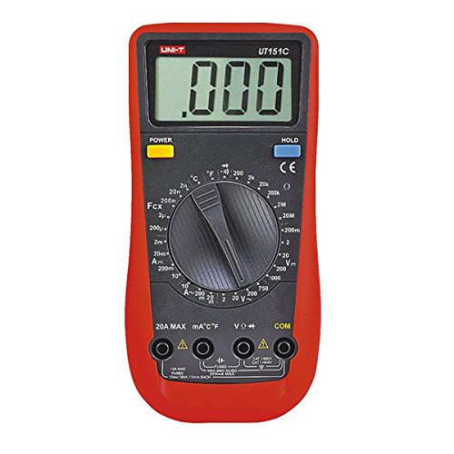
Figura 1: Davant view of the UNI-T UT151C Digital Multimeter. This image displays the LCD screen, the central rotary function switch, and the input terminals at the bottom. The 'HOLD' button is visible on the right side of the display.
- Pantalla LCD: Mostra lectures de mesura, unitats i indicadors de funció.
- Funció Interruptor rotatiu: Used to select the desired measurement function (e.g., V~, V-, A~, A-, Ω, F, °C/°F, Diode, Continuity).
- Preses d'entrada: Terminals for connecting test leads. Typically include COM (common), VΩmA (voltage, resistance, small current), and 20A (high current).
- Botó HOLD: Congela la lectura actual a la pantalla.
- Botó d'encesa: Encén o apaga el dispositiu.
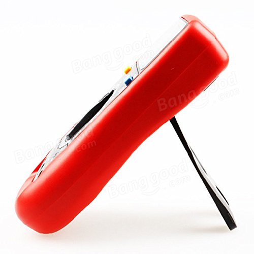
Figura 2: lateral view of the UNI-T UT151C Digital Multimeter. This image highlights the integrated kickstand, allowing the meter to be propped up for easier viewdurant l'ús.
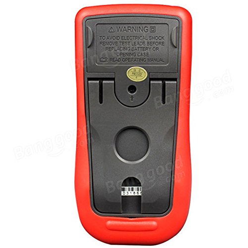
Figura 3: Enrere view of the UNI-T UT151C Digital Multimeter. This image shows the battery compartment cover and important safety warnings regarding electrical shock and battery replacement.
Configuració
1. Instal·lació de la bateria
The UNI-T UT151C requires a 9V (6F22) battery for operation. The battery is not included.
- Ensure the multimeter is powered off and disconnect any test leads.
- Localitzeu el compartiment de la bateria a la part posterior del mesurador (vegeu la figura 3).
- Unscrew the retaining screw(s) and remove the battery cover.
- Connect a new 9V battery to the battery clips, observing correct polarity.
- Col·loqueu la bateria al compartiment i torneu a col·locar la tapa, fixant-la amb el(s) cargol(s).
Nota: Replace the battery immediately when the low battery indicator appears on the display to maintain measurement accuracy.
2. Connexió dels cables de prova
Connecteu sempre el cable de prova negre al COM Connecteu el cable de prova vermell al connector d'entrada adequat segons el tipus de mesura:
- Per al voltage, resistance, capacitance, diode, continuity, and temperature measurements, connect the red lead to the VΩmA jack.
- For current measurements up to 200mA, connect the red lead to the VΩmA jack.
- For current measurements up to 20A, connect the red lead to the 20A jack.
Precaució: Incorrect lead connection can damage the meter or the circuit under test.
Instruccions de funcionament
Follow these steps for various measurement functions.
1. Encendre/apagar
Premeu el botó PODER button to turn the multimeter on. The meter features an auto power-off function to conserve battery life. To turn it off manually, press the PODER botó de nou.
2. Mesura de la tensió de CCtage (V-)
- Connecteu el cable negre a COM i el cable vermell a VΩmA.
- Set the rotary switch to the desired V- range (e.g., 2V, 20V, 200V, 1000V). If the voltage is unknown, start with the highest range and decrease as needed.
- Connect the test leads in parallel across the component or circuit to be measured.
- Llegeix el voltage valor a la pantalla LCD.
3. Mesurar AC Voltage (V~)
- Connecteu el cable negre a COM i el cable vermell a VΩmA.
- Set the rotary switch to the desired V~ range (e.g., 2V, 20V, 200V, 750V).
- Connect the test leads in parallel across the AC source or component.
- Llegeix l'AC voltage valor a la pantalla LCD.
4. Measuring DC Current (A-)
- Precaució: Always connect the meter in series with the circuit. Never connect it in parallel across a voltage source when measuring current.
- Desconnecteu l'alimentació del circuit.
- Break the circuit at the point where current is to be measured.
- For currents up to 200mA, connect the black lead to COM i el cable vermell a VΩmA.
- For currents up to 20A, connect the black lead to COM i el cable vermell a 20A.
- Set the rotary switch to the appropriate A- rang.
- Connect the test leads to complete the circuit.
- Apply power to the circuit and read the DC current value.
5. Measuring AC Current (A~)
- Follow the same safety precautions and connection steps as for DC Current measurement.
- Set the rotary switch to the appropriate A~ rang.
- Apply power to the circuit and read the AC current value.
6. Measuring Resistance (Ω)
- Ensure the circuit or component is completely de-energized before measuring resistance.
- Connecteu el cable negre a COM i el cable vermell a VΩmA.
- Poseu el commutador rotatiu a la Ω rang.
- Connecteu els cables de prova a través del component.
- Llegiu el valor de resistència a la pantalla.
7. Measuring Capacitance (F)
- Assegureu-vos que el condensador estigui completament descarregat abans de mesurar per evitar danys al mesurador.
- Connecteu el cable negre a COM i el cable vermell a VΩmA.
- Poseu el commutador rotatiu a la F (Capacitance) range.
- Connecteu els cables de prova als terminals del condensador.
- Llegiu el valor de la capacitat a la pantalla.
8. Measuring Temperature (°C/°F)
- Connect the temperature probe (if included and compatible) to the COM i VΩmA preses, observant la polaritat.
- Poseu el commutador rotatiu a la °C or °F posició.
- Place the tip of the temperature probe on or near the object whose temperature is to be measured.
- Llegiu el valor de la temperatura a la pantalla.
9. Prova de díodes
- Assegureu-vos que el díode estigui desconnectat del circuit.
- Connecteu el cable negre a COM i el cable vermell a VΩmA.
- Poseu el commutador rotatiu a la Díode símbol.
- Connecteu el cable vermell a l'ànode i el cable negre al càtode del díode. Un voltatge directetage drop (e.g., 0.5V to 0.8V for silicon diodes) will be displayed.
- Inverteix els cables. La pantalla hauria de mostrar "OL" (bucle obert) per a un díode en bon estat.
10. Prova de continuïtat
- Assegureu-vos que el circuit o component estigui desenergitzat.
- Connecteu el cable negre a COM i el cable vermell a VΩmA.
- Poseu el commutador rotatiu a la Continuïtat symbol (often shared with Diode test).
- Connect the test leads across the component or circuit path.
- If there is continuity (low resistance), the buzzer will sound, and a low resistance value will be displayed. "OL" indicates an open circuit.
11. Funció de retenció de dades
Premeu el botó MANTENIM per congelar la lectura actual a la pantalla. Premeu-lo de nou per alliberar la retenció i reprendre les mesures en directe.
Manteniment
Un manteniment adequat garanteix la longevitat i la precisió del vostre multímetre.
- Neteja: Netegeu el cas amb l'anunciamp drap i detergent suau. No utilitzeu abrasius ni dissolvents.
- Substitució de la bateria: Replace the 9V battery when the low battery indicator appears. Refer to the "Battery Installation" section for instructions.
- Substitució de fusibles: If the current measurement function fails, the fuse may need replacement. This typically requires opening the back case. Refer to the safety warnings on the back of the meter (Figure 3) and consult a qualified technician if unsure. Use only fuses of the specified type and rating.
- Emmagatzematge: If the meter is not used for an extended period, remove the battery to prevent leakage. Store the meter in a cool, dry place, away from direct sunlight and extreme temperatures.
Resolució de problemes
If you encounter issues with your UNI-T UT151C, refer to the following common problems and solutions:
| Problema | Causa possible | Solució |
|---|---|---|
| Sense pantalla o pantalla tènue | Bateria baixa o baixa | Substituïu la bateria de 9V. |
| Es mostra "OL" (sobrecàrrega) | Measurement exceeds selected range or open circuit | Select a higher range or check for an open circuit in the component/leads. |
| Lectures incorrectes | Incorrect function selected, poor lead connection, or low battery | Verify function selection, ensure leads are securely connected, or replace battery. |
| La mesura de corrent no funciona | Fusible cremat | Substituïu el fusible (vegeu la secció Manteniment). |
Especificacions
Technical specifications for the UNI-T UT151C Digital Multimeter.
| Característica | Especificació |
|---|---|
| Model | UT151C (Internal Model: 365BG1060568) |
| DC Voltage (V) | 200mV/2V/20V/200V/1000V; ±(0.5%+1) |
| Vol. ACtage (V) | 2V/20V/200V/750V; ±(0.8%+3) |
| Corrent DC (A) | 2mA/20mA/200mA/20A; ±(0.8%+1) |
| Corrent alterna (A) | 20mA/200mA/20A; ±(1%+3) |
| Resistència (Ω) | 200Ω/2KΩ/20KΩ/200KΩ/2MΩ/20MΩ; ±(1%+2) |
| Capacitat (F) | 2nF/20nF/200nF/2µF/100µF; ±(4%+3) |
| Temperatura (°C) | -40°C ~ 1000°C; ±(1%+3) |
| Temperatura (°F) | -40°F ~ 1832°F; ±(1%+4) |
| Nombre de visualitzacions | 1999 |
| Rang manual | Sí |
| Prova de díode | Sí |
| Apagat automàtic | Sí |
| Buzzer de continuïtat | Sí |
| Indicació de bateria baixa | Sí |
| Retenció de dades | Sí |
| Input Impedance for DC Voltage | ≥10MΩ |
| Font d'alimentació | 9V (6F22) Battery (not included) |
| Mida LCD | 63 mm x 29 mm |
| Color del producte | Red and Gray |
| Pes net del producte | 300 g |
Garantia i Suport
La informació sobre la garantia del producte i l'atenció al client normalment es proporciona amb la documentació de compra o a la fitxa oficial del fabricant. website. Please refer to those resources for specific details.