
EPEVER Tracer4210AN-G3
EPEVER MPPT Solar Charge Controller 40A (Tracer4210AN-G3) Instruction Manual
Brand: EPEVER | Model: Tracer4210AN-G3
1. Introducció
This manual provides detailed instructions for the installation, operation, maintenance, and troubleshooting of your EPEVER MPPT Solar Charge Controller 40A (Tracer4210AN-G3). Please read this manual thoroughly before installation and operation to ensure proper functionality and safety.
Important Safety Notice: Read carefully all the instructions and warnings in the manual before installation.
2. Producte acabatview
The EPEVER MPPT Solar Charge Controller 40A (Tracer4210AN-G3) is an advanced Maximum Power Point Tracking (MPPT) charge controller designed for off-grid solar systems. It features automatic 12V/24V system voltage recognition, a maximum PV input of 100V, and supports up to 520W for 12V battery systems or 1040W for 24V battery systems. Its common negative grounding design and upgraded ultra-quiet operation ensure efficient and reliable performance.
2.1. Aparença física

Figura 1: Frontal view of the EPEVER MPPT Solar Charge Controller 40A.

Figura 2: superior i inferior views of the controller, showing heat sink and terminal connections.
2.2. Dimensions

Figure 3: Detailed dimensions of the Tracer4210AN-G3 controller (252x180x63mm).
2.3. Components inclosos
- 1 x 40A MPPT Solar Charge Controller (Tracer4210AN-G3)
- 1 x Temperature sensor (Model: RT-MF58R47K3.81A)
- 1 x manual en anglès
3. Configuració
3.1. Eines i materials necessaris
- 12V/24V Battery (e.g., lead-acid or lithium-ion)
- Two pieces of wires for battery connection
- CC-USB-RS485-150U Communication Cable
- Tornavís
- Laptop or PC (Windows OS recommended for software)
3.2. Connexions de cablejat
Follow the connection order carefully to avoid damage. Always connect the battery first.
- Connect the positive battery terminal to the charge controller terminal marked 'Battery +'.
- Connect the negative battery terminal to the charge controller terminal marked 'Battery -'.
- Tighten the screws securely to ensure good contact.
- Verify that the LCD display on the controller powers on, indicating successful battery connection.

Figure 4: Basic wiring diagram for the solar charge controller, showing connections to battery, PV panel, and DC load.
3.3. Driver Installation for PC Communication
To communicate with the charge controller via your PC, you need to install the appropriate driver for the CC-USB-RS485-150U communication cable.
- Ensure the charge controller is powered on and the communication cable is plugged into both the controller's RS485 port and your PC's USB port.
- Locate the installation folder for the PC software (e.g., 'PCSOFTWAREFORTHESOLARCHARGECONTROLLER').
- Navigate to the 'PCTools' folder, then open the 'USBDriver' folder.
- Right-click on the 'Setup.bat' file and select 'Run as administrator'. This will automatically install the communication cable driver.
- Verify the installation by opening Device Manager on your PC. Look under 'Ports (COM & LPT)' for a device like 'XR21B1411 USB UART (COMx)', where 'x' is the assigned COM port number.
- Right-click on this device, select 'Properties', and navigate to the 'Port Settings' tab.
- If your cable label is 'CC-USB-RS485-150U', ensure the 'RS-485' checkbox is checked. Otherwise, leave it unchecked.
- Click 'Advanced' to confirm the COM port number (e.g., COM3). Remember this number for software configuration.
4. Funcionament del controlador
4.1. LCD Display Navigation
The controller features an LCD display for monitoring parameters and configuring settings. Use the buttons below the display to navigate through menus and adjust values.
4.2. Configuració del tipus de bateria
The controller supports various battery types. It is crucial to set the correct battery type for optimal charging and battery longevity.
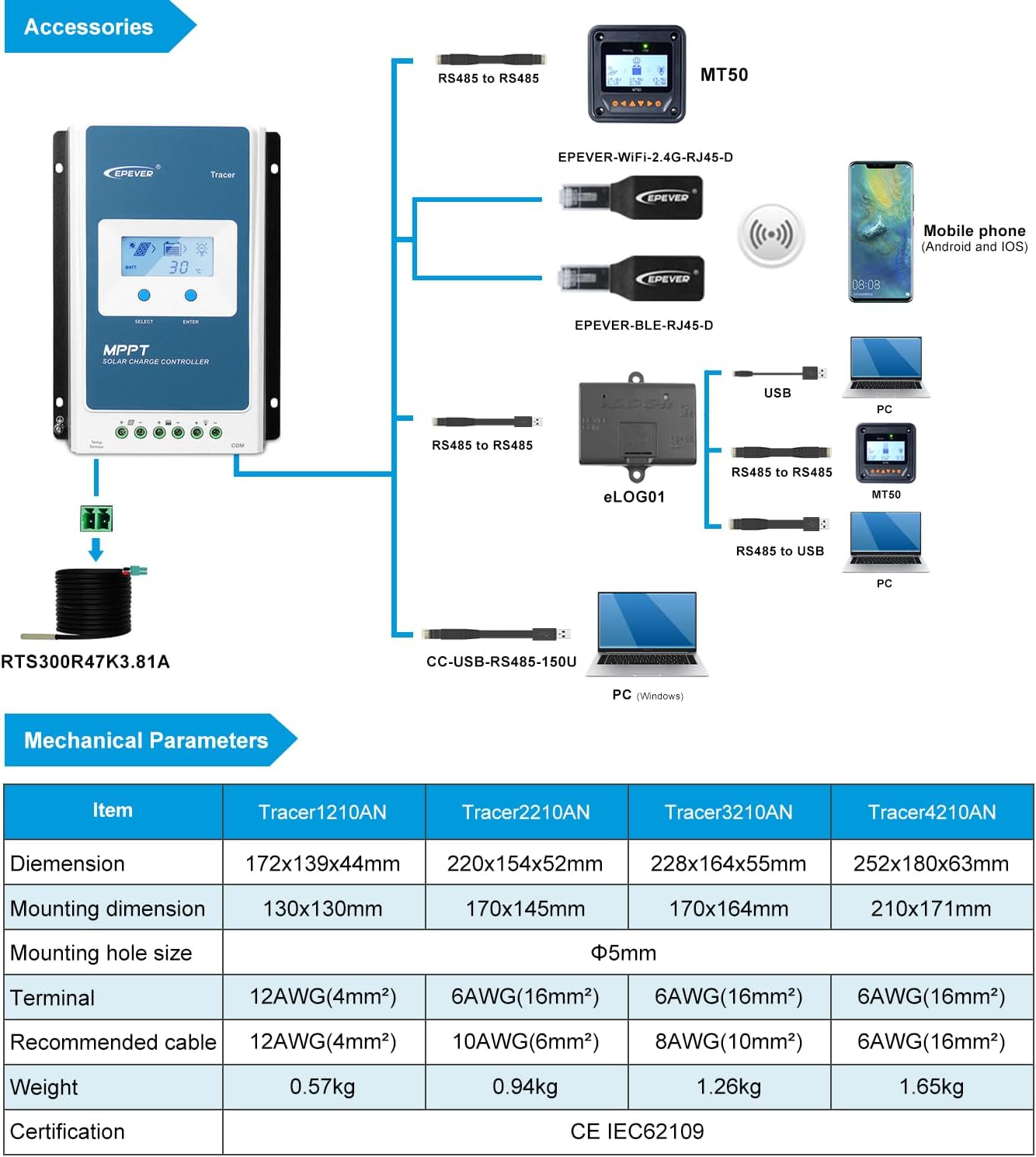
Figure 5: LCD display showing various battery type settings (Sealed, Gel, Flooded, LiFePO4, Li(NiCoMn)O2, User-defined).
4.3. Real-Time Monitoring via PC Software
The PC software allows for comprehensive real-time monitoring and parameter adjustment.
- Open the 'Solar Station' software on your PC.
- Go to the 'Port Config' menu and select 'Port Configuration'.
- In the 'Serial Port Setting' window, ensure the 'Port' dropdown matches the COM port number identified in Device Manager (e.g., COM3).
- Click the 'Add' button to add the station to your list.
- Close the 'Serial Port Setting' dialogue.
- From the main software interface, go to 'System' menu and choose 'Add Station'.
- Define the parameters of your station, ensuring you select the correct COM port from the 'Controller' tab within the station information.
- Click 'Add' to save the station.
- Once the station is successfully added, click 'Start monitoring' to begin receiving real-time data from your charge controller.
Video 1: Demonstrates how to connect the EPEVER MPPT charge controller via PC software for monitoring and configuration.
5. Manteniment
Regular maintenance ensures the longevity and optimal performance of your EPEVER MPPT Solar Charge Controller.
- Mantingueu el controlador net i lliure de pols i deixalles.
- Comproveu periòdicament totes les connexions del cablejat per verificar si estan ben ajustades i si hi ha corrosió.
- Ensure proper ventilation around the controller to prevent overheating.
- Monitor system parameters regularly using the LCD or PC software to detect any anomalies.
- Inspect the temperature sensor for proper placement and connection.
6. Solució De Problemes
This section outlines common issues and their potential solutions. For more complex problems, contact technical support.
| Problema | Causa / Solució |
|---|---|
| PV Overcurrent/Power | Ensure the open-circuit voltage of the PV array does not exceed the maximum PV open-circuit voltage. Otherwise the controller may be damaged. |
| Circuit curt de PV | Quan no estigui en estat de càrrega fotovoltaica, el controlador no es farà malbé en cas d'un curtcircuit a la matriu fotovoltaica. |
| PV inversa polaritat | When the polarity of the PV array is reversed, the controller may not be damaged and can continue to operate normally after the polarity is corrected. NOTE: If the PV array is reverse connected to the controller, 1.5 times rated controller power (watts) from the PV array, will damage the controller. |
| Càrrega inversa nocturna | Evita que la bateria es descarregui a través del mòdul fotovoltaic durant la nit. |
| Polaritat inversa de la bateria | Fully protected against battery reverse polarity; no damage to the controller will result. Correct the miswire to resume normal operation. |
| Battery Over Voltage | Quan la bateria voltage arriba al sobre voltagi desconnectar voltage, aturarà automàticament la càrrega de la bateria per evitar danys a la bateria causats per una sobrecàrrega. |
| Descàrrega excessiva de la bateria | Quan la bateria voltage arriba al baix voltagi desconnectar voltage, aturarà automàticament la descàrrega de la bateria per evitar danys a la bateria causats per una sobredescàrrega. (Qualsevol càrrega connectada al controlador es desconnectarà. Les càrregues connectades directament a la bateria no es veuran afectades i poden continuar descarregant la bateria.) |
| Sobreescalfament de la bateria | El controlador pot detectar la temperatura de la bateria mitjançant un sensor de temperatura extern. El controlador deixa de funcionar quan la seva temperatura supera els 65 °C i comença a funcionar quan la seva temperatura és inferior a 55 °C. |
| Lithium Battery Low Temperature Protection | When the temperature detected by the optional temperature sensor is lower than the Low Temperature Protection Threshold (LTPT), the controller will stop charging and discharging automatically. When the detected temperature is higher than the LTPT, the controller will be working automatically (The LTPT is 0 °C by default and can be set within the range of 10 ~ -40 °C). |
| Carregar curtcircuit | When the load is short circuited (The short circuit current is ≥ 2 times the rated controller load current), the controller will automatically cut off the output. If the load reconnects automatically five times (delay of 5s, 10s, 15s, 20s, 25s), it needs to be cleared by pressing the Load button, restarting the controller or switching from Night to the Day (nighttime = 3 hours). |
| Càrrega de sobrecàrrega | When the load is overloading (The overload current is ≥ 1.05 times the rated load current), the controller will automatically cut off the output. If the load reconnects automatically five times (delay of 5s, 10s, 15s, 20s, 25s), it needs to be cleared by pressing the Load button restarting the controller, switching from Night to Day (nighttime = 3 hours). |
| Sobreescalfament del controlador* | El controlador és capaç de detectar la temperatura dins de la bateria mitjançant un sensor remot opcional. El controlador deixa de funcionar quan la seva temperatura supera els 85 °C i comença a funcionar quan la seva temperatura és inferior a 75 °C. |
| TVS High Voltage Transitoris | El circuit intern del controlador està dissenyat amb Transient Voltage Supressors (TVS) que només poden protegir contra alt voltagEls polsos de sobretensió amb menys energia. Si el controlador s'ha d'utilitzar en una zona amb llamps freqüents, es recomana instal·lar un descargador de sobretensions extern. |
*When the internal temperature is 81°C, the reducing power charging mode which reduce the charging power of 5%,10%,20%,40% every increase 1°Cis turned on. If the internal temperature is greater than 85°C, the controller will stop charging. But while the temperature decline to be below 75°C, the controller will resume.
7. Especificacions
| Característica | Valor |
|---|---|
| Model | Tracer4210AN (Upgraded version) |
| Rated Charge and Discharge Current | 40A |
| Sistema nominal Voltage | 12V/24V DC auto work |
| Màx. Potència d'entrada fotovoltaica | 520W for 12V battery system or 1040W for 24V battery system |
| Màx. Circuit obert PV Voltage | 100V (at minimum operating environment temperature) 92V (at 25℃ environment temperature) |
| Supported Lead-acid Battery Types | Sealed, Gel(AGM), Flooded, User(9~17V@12V; 18~34V@ 24V) |
| Supported Li-ion Battery Types | LiFePO4 (4s/12V; 8s/24V), Li(NiCoMn)O2 (3s/12V; 6s/24V), User(9~34V) |
| Posada a terra | Negatiu comú |
| MPPT Voltage Rang | (Bateria voltage + 2V) a 72V |
| Eficiència de seguiment | ≥99.5% |
| Màx. Eficiència de conversió | 98% |
| Temperatura de l'entorn de treball | -25℃~+50℃ (100% input and output) |
| Temperatura d'emmagatzematge | -20°C -- +70°C/-4°F -- 158°F |
| Temps de retroil·luminació LCD | 60s (Default), Range: 0-999s (0s: the backlight is ON all the time) |
| Interfície RS485 | 5VDC / 200mA |
| Terminals del controlador | #6 AWG (16mm2) |
| Recommended Wire Cable | #6 AWG (16mm2) |
| Dimensió | 252 * 180 * 63 mm (9.92 x 7.09 x 2.48 polzades) |
| Pes | 1.65 KG (3.63 lliures) |
| Tipus de visualització | LCD |
| Tancament | IP30 |
8. Accessoris opcionals
Enhance the functionality and monitoring capabilities of your EPEVER MPPT Solar Charge Controller with these optional accessories:
- MT50/MT52 Remote Meter: For remote display and parameter setting.
- Adaptador WiFi: For wireless monitoring and control via mobile app.
- BLE (Bluetooth Low Energy) Adapter: For Bluetooth connectivity and mobile app control.
- eLOG01: External logger for data storage.
- USB-RS485 Cable (CC-USB-RS485-150U): For PC communication and software configuration.
9. Garantia i Suport
EPEVER products are backed by a commitment to quality and customer satisfaction. As an official authorized sales agent for the EPEVER brand, GolandCentury offers the latest versions of controllers and accessories.
Our dedicated technical support team provides free assistance to ensure you have a seamless experience with your solar products. For any technical inquiries or support needs, please contact our service centers located in Chicago (USA), Munich (Germany), Toronto (Canada), and Melbourne (Australia).
Ask a question about this manual
Ask about setup, troubleshooting, compatibility, parts, safety, or missing instructions. Manuals+ will review the question and use this page’s manual context to help answer it.