
Introducció
This manual provides instructions for the EPEVER Tracer AN Series MPPT Solar Charge Controller, specifically the 10A model (Tracer1210AN). This controller utilizes advanced Maximum Power Point Tracking (MPPT) technology to optimize solar energy harvesting and manage battery charging efficiently.

Davant view of the EPEVER Tracer AN Series 10A MPPT Solar Charge Controller, showing the LCD display and control buttons.
Key features of this controller include:
- Advanced MPPT (Maximum Power Point Tracking) technology, with efficiency no less than 99.5% and a maximum conversion efficiency of 98%.
- Features an LCD display for real-time operational status.
- Precise tracking of the photovoltaic array's Maximum Power Point (MPP) in all situations, maximizing solar energy harvest over time and significantly improving energy efficiency.
- Equipped with a Modbus communication protocol interface, allowing for convenient expansion of applications and monitoring in various fields such as telecommunication stations, home systems, street lighting systems, and environmental monitoring systems.
- Supports PC monitoring and external display units like the MT50, enabling real-time data control and parameter settings. Software updates are also supported.
Instal·lació i cablejat
Proper installation and wiring are crucial for the safe and efficient operation of your solar charge controller. Please follow these guidelines carefully.
Esquema de cablejat

This diagram illustrates the correct connection sequence: 1. Battery, 2. Load, 3. PV Array. Disconnect in reverse order.
Precaucions importants
- PRECAUCIÓ: When wiring the controller, do not close the circuit breaker or fuse. Ensure that the positive ("+") and negative ("-") leads are connected correctly.
- PRECAUCIÓ: A fuse, with a current rating 1.25 to 2 times the controller's rated current, must be installed on the battery side. The distance from the battery should not exceed 150 mm.
- PRECAUCIÓ: If the controller is used in an area with frequent lightning strikes or is an unattended area, an external surge arrester must be installed.
- PRECAUCIÓ: Si s'ha de connectar un inversor al sistema, connecteu l'inversor directament a la bateria, no al costat de càrrega del controlador.
Funcionament
Pantalla LCD acabadaview
The integrated LCD provides real-time information about the system's status, allowing you to monitor various parameters.

This image displays the various screens available on the LCD, including PV Input Voltage, Charging Current, Energy Generation, Load Working Mode, Battery Voltage, Battery Current, Load Usage Statistics, Discharge Current, and Temperature.
Configuració del tipus de bateria
Follow these steps to configure the battery type via the LCD display:

This image illustrates the sequence for setting the battery type.
- Pas 1: Premeu el botó SELECCIONA button to navigate to the battery voltage interfície.
- Pas 2: Manteniu premut el botó ENTRAR button until the battery type interface flashes.
- Pas 3: Premeu el botó SELECCIONA button to modify the battery type. Options include Sealed (default), Gel, Flooded, LCNM3S, LFP8S, LFP4S, LCNM6S, LCNM7S, and User-defined.
- Pas 4: Premeu el botó ENTRAR botó per confirmar la selecció.
Icones de la interfície
The following table explains the meaning of the icons displayed on the controller's interface.

This image provides a visual guide to the various icons and their corresponding statuses for the PV array, battery, and load.
| Item | Icona | Estat |
|---|---|---|
| Matriu fotovoltaica | Dia | |
| Matriu fotovoltaica | Nit | |
| Matriu fotovoltaica | Sense càrrega | |
| Matriu fotovoltaica | Carregant | |
| Matriu fotovoltaica | PV | PV Voltage, corrent, potència |
| Bateria | Battery capacity, in Charging | |
| Bateria | BATT. | Voltage, Corrent, Temperatura |
| Bateria | BATT. TIPUS | Tipus de bateria |
| Carrega | Carrega activat | |
| Carrega | Carrega OFF | |
| Carrega | CÀRREGA | Volum de càrregatage, Actual, Mode de càrrega |
Manteniment
To ensure optimal performance and longevity of your EPEVER MPPT solar charge controller, regular maintenance is recommended.
- Inspeccioneu periòdicament totes les connexions del cablejat per assegurar-vos que estiguin ben fixades i que no presentin corrosió.
- Keep the controller clean and free from dust and debris. Ensure proper ventilation around the unit.
- Monitor the LCD display for any error codes or unusual readings. Refer to the troubleshooting section if issues arise.
- Ensure the ambient temperature around the controller remains within its specified operating range to prevent overheating.
Resolució de problemes
This section provides guidance for common issues you might encounter with your solar charge controller.
- El comandament no es carrega: Check PV array connections, ensure sufficient sunlight, verify battery connections, and check for blown fuses. Confirm that the PV input voltage està dins del rang de funcionament del controlador.
- Baix corrent de càrrega: Inspect PV panel cleanliness, check for shading, and confirm battery type settings are correct. Ensure all connections are secure and there is no excessive voltage gota.
- La pantalla LCD no funciona: Verify battery connection and voltage. Ensure the controller is receiving power. If the issue persists, contact support.
- Load Output Off (Over-Discharge Protection): If the load output is off, the battery voltage may be too low. The load will automatically reconnect once the battery recovers to a safe voltage nivell.
- Sobreescalfament: Ensure the controller has adequate ventilation and is not installed in an enclosed space without airflow. Reduce load if necessary.
Especificacions tècniques
Key technical details for the EPEVER Tracer1210AN MPPT Solar Charge Controller.
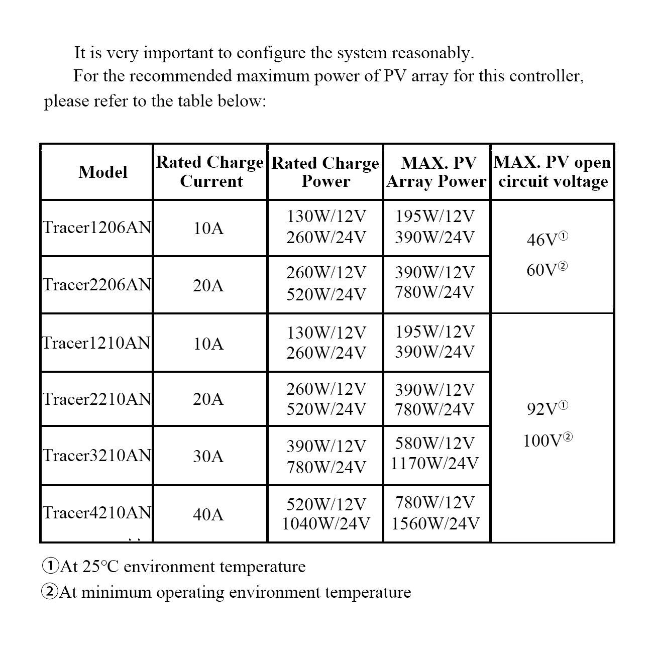
This image provides a detailed specification table for the Tracer AN series, including the Tracer1210AN model.
| Característica | Detall |
|---|---|
| Model | Tracer1210AN |
| Marca | SEMPRE |
| Corrent de càrrega nominal | 10A |
| Volum del sistematage | 12V / 24V DC Auto Identification |
| Rated Charge Power (12V) | 130W |
| Rated Charge Power (24V) | 260W |
| Max. PV Array Power (12V) | 195W |
| Max. PV Array Power (24V) | 390W |
| Màx. Circuit obert PV Voltage | 92V (at 25°C environment temperature), 100V (at minimum operating environment temperature) |
| Dimensions (L x A x A) | 17.2 x 13.9 x 4.4 cm |
| Pes | 720 grams |
| Material | Plàstic |
| Tipus de visualització | LCD |
| Temperatura de funcionament | Fins a 45°C |
| GTIN / UPC | 680465249352 |
Garantia i Suport
For product support, please refer to the official EPEVER website or contact your local distributor. Detailed warranty information is typically provided with the product packaging or available on the manufacturer's weblloc.
The controller supports PC monitoring and external display units (e.g., MT50) for advanced data control and parameter settings. Software updates are also supported to ensure your controller remains up-to-date with the latest features and improvements.

This image shows optional accessories (not included) such as RS485 communication cables, Wi-Fi and Bluetooth modules (eBox-WiFi-01, eBox-BLE-01), USB adapters, and the MT50 external display unit, which enable PC and mobile app monitoring. A temperature sensor (RTS300R47K3.81A) is also depicted.