
1. Producte acabatview
The EPEVER Tracer AN Series MPPT Solar Charge Controller is designed to manage power flow from solar panels to batteries, ensuring efficient charging and protecting the battery from overcharge and over-discharge. This 50A model supports 12V, 24V, 36V, and 48V automatic system voltage identification and features advanced Maximum Power Point Tracking (MPPT) technology for optimal solar energy harvesting. It is suitable for various off-grid solar applications.
Característiques principals:
- Tecnologia MPPT avançada: Ultra-fast tracking speed with efficiency no less than 99.5% for maximum power point utilization.
- Adaptive Three-Stage Càrrega: Extends battery life and improves system performance.
- Automatic System Voltage Identificació: Supports 12V/24V/36V/48V systems.
- Compatibilitat amb diversos tipus de bateria: Compatible with Sealed, Gel, Flooded, and User-defined battery types.
- Interfícies de comunicació: Standard Modbus protocol with RS485 interface for monitoring and parameter setting via phone apps, MT50 remote meter, and PC software.
- Operació en paral·lel: Dual RS485 ports (RJ45) support up to 8 units in parallel for system expansion.
- Protecció integral: Includes protection against overcharge, over-discharge, reverse polarity, and more.
2. Components del producte
El paquet normalment inclou els components següents:
- EPEVER Tracer AN Series MPPT Solar Charge Controller (Tracer5415AN)
- Mesurador remot MT50
- Sensor de temperatura remot (RTS)
- PC Communication Cable (RS485)
- Accessoris de muntatge (cargols, tacs de paret)

3. Controller Features and Ports
Familiarize yourself with the various components and connection points of the solar charge controller.

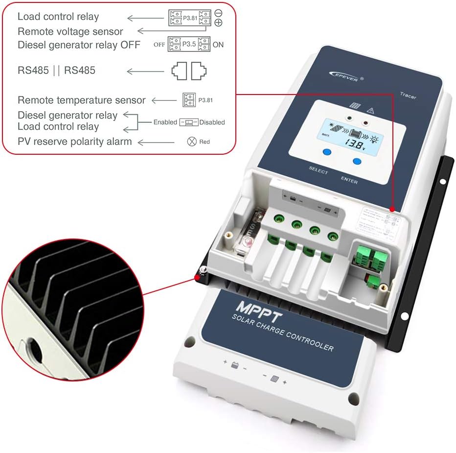
- Charging LED indicator: Indica l'estat de càrrega.
- Botó SELECCIONA: S'utilitza per a la navegació i selecció de menús.
- Fusible: Overcurrent protection for the battery circuit.
- Terminal de terra: For system grounding.
- Fault LED indicator: Indicates system faults or errors.
- LCD: Displays system parameters and status.
- Botó ENTER: Used to confirm selections and enter menus.
- RBVS Port: Volum de bateria remotatage Sensor port.
- Utility/Generator relay ON: Output for controlling external utility/generator.
- RS485 port (5VDC/200mA): Communication port for accessories.
- RTS Port: Remote Temperature Sensor port.
- Generator and load relay enable: Control for generator and load relays.
- PV reverse polarity alarm indicator: Alerts to incorrect PV connection.
- Load control relay: Output for controlling DC loads.
- Utility/Generator relay OFF: Output for controlling external utility/generator.
- PV Terminals: Connection points for solar panel input.
- Terminals de bateria: Connection points for battery bank.
4. Guia d'instal·lació
4.1 Precaucions de seguretat
- Ensure all connections are secure and correct to prevent damage or injury.
- Disconnect all power sources (solar panels and battery) before installation or maintenance.
- Install the controller in a well-ventilated area, away from direct sunlight and moisture.
- Maintain adequate clearance around the controller for heat dissipation.
4.2 Muntatge del controlador
Mount the controller vertically on a non-flammable surface, ensuring the terminals are easily accessible. Use the provided mounting accessories.
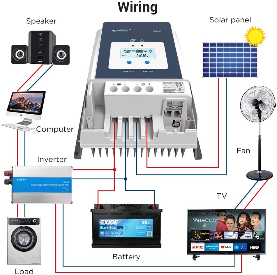
4.3 Connexions de cablejat
Follow the wiring sequence carefully to avoid damage. Connect the components in the order specified below:
- Connecteu la bateria: Connect the battery to the controller's battery terminals. Ensure correct polarity (+ to + and - to -). The controller will detect the system voltage.
- Connecteu el panell solar: Connect the solar panel to the controller's PV terminals. Ensure correct polarity.
- Connecteu la càrrega de CC (opcional): Connect the DC load to the controller's load terminals.
- Connect Remote Accessories (Optional): Connect the MT50 remote meter, RTS, and RS485 communication cable as needed.

5. Instruccions de funcionament
5.1 Engegada inicial
After connecting the battery, the controller will power on and display system information on its LCD. The charging LED will indicate the charging status.
5.2 Using the MT50 Remote Meter
The MT50 remote meter provides a comprehensive interface for monitoring system data and configuring parameters. Connect the MT50 to the controller via the RS485 port. The MT50 will automatically identify the controller and display real-time data.

5.3 Configuració dels paràmetres
Use the SELECT and ENTER buttons on the controller or the MT50 remote meter to navigate menus and adjust parameters such as battery type, charging voltage limits, and load control settings. Refer to the detailed user manual for specific menu structures and parameter definitions.
5.4 Communication with PC Software
The controller supports communication with PC software via the RS485 port and the provided communication cable. This allows for advanced monitoring, data logging, and parameter configuration. Download the latest software from the EPEVER official weblloc.
6. Manteniment
Un manteniment regular garanteix un rendiment òptim i una llarga vida útil del controlador de càrrega solar.
- Comproveu les connexions: Periodically inspect all wiring connections for tightness and corrosion.
- Netegeu el controlador: Mantingueu el controlador net i lliure de pols i brutícia. Feu servir un drap sec per netejar-lo.
- Inspeccionar per danys: Check for any physical damage to the controller, cables, or terminals.
- Monitoritzar el rendiment: Regularly check system parameters via the LCD, MT50, or PC software to ensure normal operation.
7. Solució De Problemes
This section provides basic troubleshooting steps for common issues. For more complex problems, consult the detailed product manual or contact technical support.
Problemes comuns i solucions:
- El controlador no s'encén:
- Check battery connections and ensure correct polarity.
- Comproveu el volum de la bateriatage està dins del rang de funcionament del controlador.
- Check the battery fuse.
- Indicació de no càrrega:
- Ensure solar panels are connected correctly and receiving sufficient sunlight.
- Comprova el volum d'entrada PVtage i corrent.
- Comproveu el volum de la bateriatage is below the charging setpoint.
- La càrrega no funciona:
- Check load connections and ensure correct polarity.
- Verify load control settings on the controller or MT50.
- Assegureu-vos que la bateria voltage està per sobre del baix voltage disconnect (LVD) threshold.
- Errors de comunicació:
- Check RS485 cable connections.
- Ensure the MT50 or PC software is correctly configured.
8. Especificacions tècniques
Detailed technical parameters for the EPEVER Tracer5415AN MPPT Solar Charge Controller.

| Paràmetre | Value (Tracer5415AN) |
|---|---|
| Sistema nominal Voltage | 12/24/36/48VDC Auto |
| Volum d'entrada de bateriatage Rang | 8V ~ 68V |
| Tipus de bateria | Sealed(Default)/Gel/Flooded/User |
| Fusible de la bateria | 80A/58V |
| Corrent de càrrega nominal | 50A |
| Potència de càrrega nominal | 625W/12V, 1250W/24V, 1875W/36V, 2500W/48V |
| Màx. Circuit obert PV Voltage | 150 V |
| MPP Voltage Rang | (Bateria Voltage +2V) ~ 108V |
| Eficiència de seguiment | ≥99.5% |
| Màx. Eficiència de conversió | 98.30% |
| Eficiència a plena càrrega | 97.80% |
| Coeficient de compensació de temperatura | -3mV/°C/2V (per defecte) |
| Autoconsum | 98mA/12V; 60mA/24V; 50mA/36V; 46mA/48V |
| Posada a terra | Arrel negatiu comú |
| Interfície RS485 | RS485 (RJ45) |
| Temps de retroil·luminació LCD | Default: 60S, Range: 0 ~ 999S |
| Interval de temperatura ambient | -25°C ~ +60°C (Derate above 45°C) |
| Tancament | IP20 |
| Dimensions (L x A x A) | 261 x 216 x 119 mm (aprox.) |
| Pes de l'article | 4.46 kg (9.81 lliures) |
9. Dimensions del producte
Physical dimensions of the solar charge controller and the MT50 remote meter.
9.1 Dimensions del controlador

9.2 MT50 Remote Meter Dimensions
10. Aplicació Examples
The EPEVER Tracer AN Series MPPT Solar Charge Controller is versatile and can be used in various solar power systems.

11. Garantia i Suport
For warranty information, technical support, or service inquiries, please refer to the documentation included with your product or visit the official EPEVER website. You can also find support resources and contact information on the EPEVER Brand Store on Amazon.
12. Vídeos de productes
No s'han trobat vídeos oficials del venedor a les dades proporcionades per a aquest model.