
1. Introducció
This manual provides essential instructions for the installation, operation, and maintenance of your EPEVER 45A Solar Charge Controller. This device is designed to manage the power flow from your solar panels to your battery bank, ensuring efficient charging and protecting your batteries from overcharge and over-discharge. It features an LCD display for real-time monitoring and dual USB outputs for charging compatible devices.
2. Instruccions de seguretat
Please read and understand all safety instructions before installation and operation to prevent injury and damage to the controller or system components.
- Connecteu sempre la bateria al controlador de càrrega primer to allow the controller to recognize the system voltage.
- Ensure correct polarity when connecting components. Pay close attention to the "+" and "-" terminals. Incorrect wiring can cause damage.
- Do not insert fuses or turn on breakers during the initial installation process.
- Install the battery fuse as close to the battery as possible, ideally within 150mm.
- The VS AU series controller is a common positive ground device. Any positive connection of solar, load, or battery can be earth grounded if required.
- If an inverter or other load with a large starting current is necessary, connect it directly to the battery, not to the controller's load terminals.
- Assegureu-vos que hi hagi una ventilació adequada al voltant del controlador per evitar el sobreescalfament.
3. Producte acabatview
The EPEVER 45A Solar Charge Controller integrates advanced digital techniques for efficient solar energy management. It features a clear LCD display and user-friendly buttons for easy operation.
3.1 Característiques clau
- High-quality components from ST, IR, and Infineon for reliability and extended lifespan.
- LCD display for real-time monitoring of solar panel and battery performance, including energy statistics.
- Dual USB charging outputs (5V 2.4A total) for mobile devices.
- Supports three charging options: Sealed, Gel, and Flooded batteries.
- 3-StagCàrrega PWM intel·ligent: a granel, augmentar / igualar, flotar.
- Multiple load control modes: Light control, Light Time control, Dual Time control.
- Comprehensive protection features: PV Reverse Polarity, Battery Reverse Polarity, Battery Over Voltage, Battery Over Discharge, Battery Overheating, Load Short Circuit, Load Overload, Controller Overheating.
3.2 Components del controlador
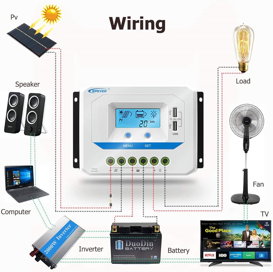
Figura 1: EPEVER 45A Solar Charge Controller Components. This diagram labels the various parts of the controller, including the LCD screen, control buttons (MENU, SET), dual USB charging ports, temperature sensor port (RTS), and the connection terminals for solar panels, battery, and load.

Figura 2: Dual USB Output Ports. The controller features two 5V 2.4A USB ports for convenient charging of external devices.
4. Configuració i instal·lació
Follow these steps carefully to install your solar charge controller. Ensure all connections are secure and correct to prevent damage.
4.1 Wiring Sequence
- Connecteu la bateria: Connect the battery to the charge controller's battery terminals. Ensure correct polarity. The controller will automatically detect the system voltage (12V/24V/36V/48V).
- Connecteu el panell solar: Connect the solar panel to the charge controller's solar panel terminals. Ensure correct polarity.
- Connect the Load: Connect the DC load to the charge controller's load terminals. Ensure correct polarity.
When disconnecting the system, reverse the order: disconnect the load first, then the solar panel, and finally the battery.

Figura 3: System Wiring Diagram. This diagram shows the recommended connection order: battery first, then solar panel, then load. It also highlights the importance of correct positive and negative connections.
Figura 4: Example Wiring for a Solar System. This illustration provides a visual guide for connecting a solar panel, battery, and various DC loads (such as a fan, TV, and speakers) to the EPEVER solar charge controller.
5. Instruccions de funcionament
The controller's LCD display provides real-time system information, and the buttons allow for configuration and navigation.
Pantalla LCD i botons 5.1
The LCD screen shows various parameters such as PV voltage, corrent de càrrega, volum de bateriatage, load current, and energy statistics. Use the MENÚ i SET buttons to navigate through the display interfaces and adjust settings.

Figura 5: Browse Interface. This image illustrates the different screens accessible via the MENU and SET buttons, displaying parameters like PV voltage, current, generated energy, load status, battery voltage, i temperatura.
5.2 Selecció del tipus de bateria
The controller supports Sealed, Gel, and Flooded battery types. Ensure the correct battery type is selected in the settings for optimal charging performance and battery longevity. Refer to the detailed manual for specific steps on how to change this setting.
5.3 Modes de control de càrrega
The controller offers multiple load control modes:
- Control de la llum: The load turns on at dusk and off at dawn.
- Light Time Control: The load turns on at dusk and stays on for a set number of hours.
- Dual Time Control: Allows for two separate time periods for load operation.
These modes are configurable via the controller's interface. Consult the full product manual for detailed programming instructions.
6. Manteniment
Regular maintenance ensures the longevity and optimal performance of your solar charge controller and system.
- Inspeccionar connexions: Periodically check all wiring connections for tightness and corrosion. Loose connections can cause resistance and heat buildup.
- Netegeu el controlador: Keep the controller clean and free from dust and debris. Ensure ventilation openings are not blocked.
- Comproveu l'estat de la bateria: Monitor de vol de la bateriatage and condition regularly. Ensure batteries are properly maintained according to their manufacturer's guidelines.
- Condicions ambientals: Ensure the controller is installed in a dry, well-ventilated area, away from direct sunlight and extreme temperatures.
7. Solució De Problemes
This section addresses common issues you might encounter with your solar charge controller.
| Problema | Causa possible | Solució |
|---|---|---|
| Sense pantalla a la pantalla LCD | Bateria no connectada o de baix volumtage; polaritat inversa. | Comproveu les connexions de la bateria i el voltage. Ensure correct polarity. Charge battery if voltage és massa baixa. |
| La bateria no es carrega | Solar panel not connected; low solar input; reverse PV polarity; battery full. | Check solar panel connections and ensure adequate sunlight. Verify PV polarity. Controller stops charging when battery is full. |
| La càrrega no funciona | Load disconnected; overload; short circuit; low battery voltage; load control mode settings. | Check load connections. Reduce load if overloaded. Check for short circuits. Ensure battery voltage is above cut-off. Verify load control mode settings. |
| Sobreescalfament del controlador | Poor ventilation; excessive load/charging current. | Ensure proper airflow around the controller. Reduce load or charging current if possible. |
8. Especificacions
Detailed technical specifications for the EPEVER 45A Solar Charge Controller (Model 45A48V).

Figura 6: Technical Specifications for 48V Models. This table provides detailed specifications for the 48V compatible models, including the 45A48V, covering electrical parameters and environmental ratings.
| Especificació | Valor |
|---|---|
| Model | 45A48V |
| Corrent nominal de càrrega/descàrrega | 45A |
| Classificació del sistema Voltage | 12V/24V/36V/48V Automàtic |
| Volum d'entrada de bateriatage Rang | 9 V ~ 64 V |
| Màx. Circuit obert PV Voltage | 96 V |
| Tipus de bateria | Sealed (Default) / Gel / Flooded |
| Posada a terra | Comú positiu |
| Sortida USB | 5 VDC/2.4 A (total) |
| Temperatura de l'entorn de treball | -25°C to +55°C (Product can work continuously at full load) |
| Tancament | IP30 |
| Dimensions (L x A x A) | 194 mm x 118 mm x 64 mm (aprox.) |
| Pes de l'article | 0.91 kg (2.01 lliures) |
| UPC | 732376582681, 732376583510 |
9. Garantia i Suport
For warranty information and technical support, please refer to the official EPEVER weblloc web o poseu-vos en contacte amb el vostre distribuïdor autoritzat. Conserveu el rebut de compra com a comprovant de compra per a reclamacions de garantia.
També podeu visitar el EPEVER Store on Amazon per a recursos addicionals i informació de contacte.