
1. Introducció i finalview
This manual provides essential information for setting up, operating, and maintaining your DORHEA ESP32 38-Pin Narrow Development Board and its accompanying Breakout Board. The ESP32 is a versatile microcontroller with integrated Wi-Fi and Bluetooth capabilities, ideal for Internet of Things (IoT) projects, embedded systems, and various electronic applications. The breakout board simplifies connections to external components.
2. Característiques del producte
- Disseny compacte: Small volume and narrow form factor for easy integration into various products.
- Powerful Microcontroller: Features 2 Tensilica LX6 cores, clocked at up to 240 MHz, and 512 KB SRAM.
- Connectivitat sense fils: Supports Wi-Fi (802.11bgn) and Bluetooth (Classic and LE).
- Múltiples modes de funcionament: Supports AP, STA, and AP+STA modes for flexible network configurations.
- Suport de programació: Compatible with Lua programming and FreeRTOS.
- Interfície fàcil d'utilitzar: Includes reset and boot buttons for easy firmware installation.
- GPIO Expansion: The breakout board expands one GPIO pin of the ESP32 development board to two, facilitating smart home DIY projects.
- Stable Connections: Double-layer PCB design on the expansion board ensures stable and reliable signal transmission.
3. Configuració
Follow these steps to prepare your ESP32 Development Board and Breakout Board for use:
- Desempaquetar components: Carefully remove the ESP32 development boards and breakout boards from their packaging.
- Inspect Boards: Check for any visible damage or manufacturing defects.
- Mount ESP32 on Breakout Board: Align the pins of the ESP32 38-Pin Narrow version development board with the corresponding sockets on the breakout board. Gently press down until the ESP32 board is securely seated.
- Connectar l'alimentació: Connect the ESP32 board to your computer using a compatible USB cable. This will provide power and enable communication for programming.
- Instal·lació de programari: Install the necessary drivers and development environment (e.g., Arduino IDE with ESP32 board support, or ESP-IDF) on your computer. Refer to online resources for detailed software setup guides.
Nota: The breakout board is designed specifically for the 38-Pin narrow version of the ESP32. It is not compatible with the ESP-WROOM-32 DevKit V1 version. Please confirm your ESP32 board's pin width matches the breakout board's design.

Image: The ESP32 Development Board being inserted into the Breakout Board, illustrating the connection process.
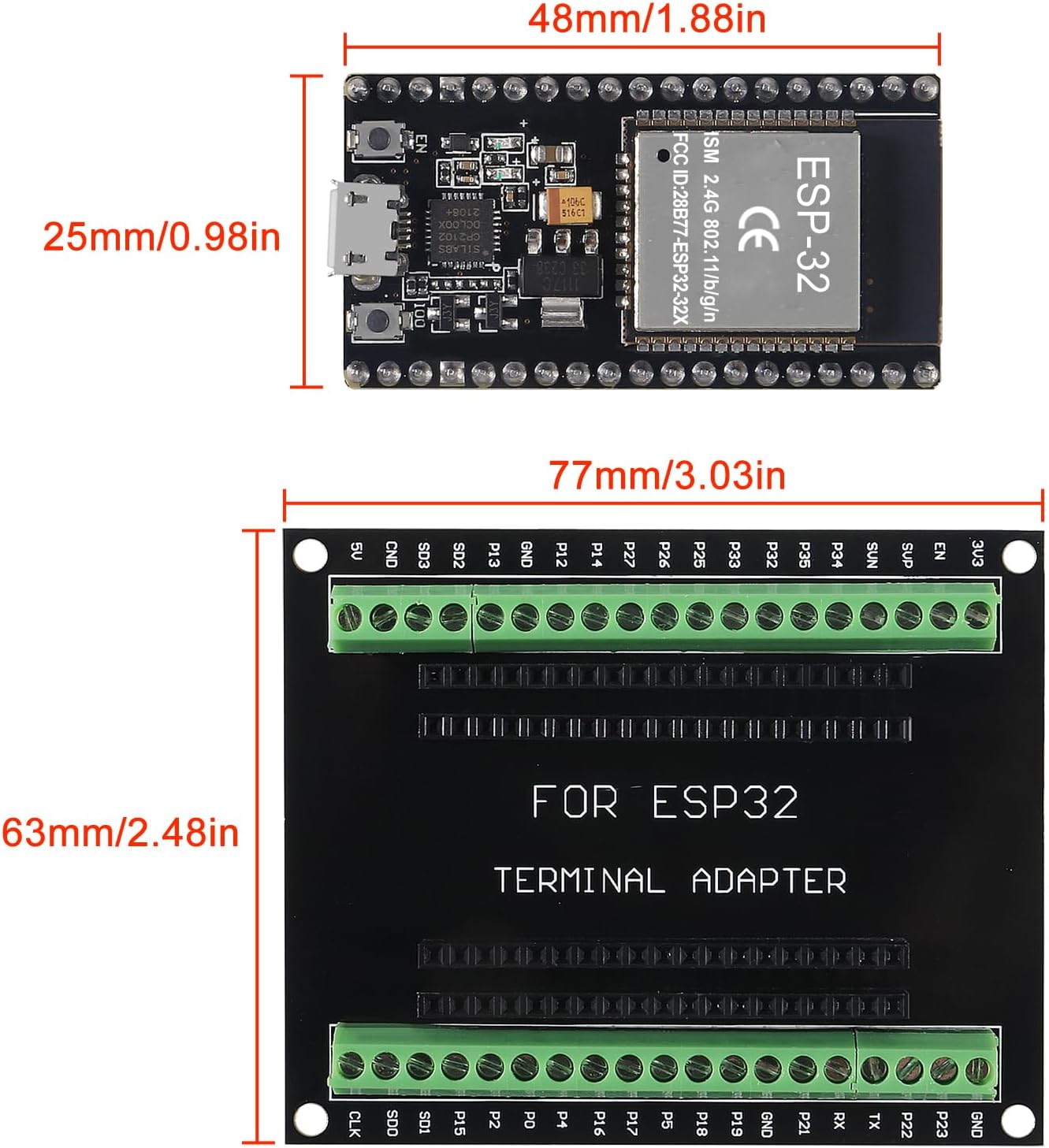
Image: Technical drawing showing the dimensions of the ESP32 Development Board and the Breakout Board, including pin spacing.
4. Instruccions de funcionament
The ESP32 Development Board is programmed using various Integrated Development Environments (IDEs) and programming languages. The most common methods include the Arduino IDE and the ESP-IDF (Espressif IoT Development Framework).
- Programació: Write your code in your chosen IDE. The ESP32 supports C/C++ (via Arduino IDE or ESP-IDF) and MicroPython/Lua.
- Upload Code: Connect the board to your computer via USB. Select the correct board and port in your IDE, then upload your compiled code.
- Alimentació de la Junta: The board can be powered via the USB port or through the VIN pin (typically 5V). Ensure the power supply is within the specified voltage gamma.
- Using GPIO Pins: Connect sensors, actuators, and other peripherals to the GPIO pins on the breakout board. Refer to the GPIO Pinout section for specific pin functions.
- Configuració de la xarxa: Utilize the Wi-Fi and Bluetooth capabilities to connect your projects to networks or other devices. Configure AP, STA, or AP+STA modes as required by your application.
Video: A demonstration of the ESP32 ESP32S module, showcasing its physical appearance and key components.
Vídeo: Un breu resumview highlighting the details and features of the ESP32 Development Board.
5. Pinout de GPIO
The ESP32 features a rich set of General Purpose Input/Output (GPIO) pins, each capable of various functions. The breakout board provides easy access to these pins.
| Funció | Available GPIO Numbers |
|---|---|
| ADC (Analog Signal Sampling) | 32, 33, 34, 35, 36, 39 |
| DAC (Analog Output) | 25, 26 |
| UART (Serial Communication) | 1 (TX0), 3 (RX0), 10 (TX1), 9 (RX1), 17 (TX2), 16 (RX2) |
| SPI (SPI Bus Interface) | hspi (14, 12, 13, 15), vspi (23, 19, 18, 5) |
| I2C (I2C Bus Interface) | SDA (21), SCL (22) (Note: MicroPython does not implement I2C in hardware) |
This table outlines the primary functions of key GPIO pins. Always consult the ESP32 datasheet for comprehensive pin details and alternative functions.
6. Manteniment
To ensure the longevity and optimal performance of your ESP32 Development Board and Breakout Board, observe the following maintenance guidelines:
- Manejar amb cura: Avoid dropping or subjecting the boards to physical shock.
- Descàrrega estàtica: Always handle the boards in a static-safe environment to prevent damage to sensitive electronic components.
- Mantenir sec: Protect the boards from moisture and liquids, which can cause short circuits and corrosion.
- Neteja: Keep the boards free from dust and debris. Use a soft, dry brush or compressed air for cleaning. Avoid using liquids or abrasive materials.
- Emmagatzematge adequat: When not in use, store the boards in their original anti-static packaging or a protective enclosure.
7. Solució De Problemes
If you encounter issues with your ESP32 Development Board, consider the following troubleshooting steps:
- La placa no s'encén: Ensure the USB cable is securely connected and providing power. Try a different USB port or cable.
- Failed Code Upload:
- Verify that the correct board type and COM port are selected in your IDE.
- Assegureu-vos que tots els controladors necessaris estiguin instal·lats.
- Press and hold the 'BOOT' button while pressing and releasing the 'EN' (Reset) button, then release 'BOOT' to enter bootloader mode for uploading.
- Program Not Running Automatically After Power-Up: Some ESP32 boards may require a manual reset after power-up to run the uploaded program. If your program does not start automatically, press the 'EN' (Reset) button. This can sometimes be related to specific ground pin configurations; ensure proper grounding if you are using external power sources or custom circuits.
- Connexions inestables: If using the terminal adapter, ensure wires are securely fastened by tightening the screws. For pin headers, confirm that all pins are fully inserted and making good contact.
- Problemes de connectivitat Wi-Fi/Bluetooth: Check your code for correct network credentials and configuration. Ensure the board is within range of the access point or Bluetooth device.
- GPIO Malfunction: Double-check your wiring against the pinout diagram. Verify that the GPIO pins are configured correctly in your code (input/output, pull-up/down resistors).
8. Especificacions
| Característica | Detall |
|---|---|
| Marca | DORHEA |
| Nom del model | DORHEA ESP32 |
| Microcontrolador | ESP-WROOM-32 (ESP32-D0WD-V3) |
| Nuclis de CPU | 2 Tensilica LX6 cores |
| Velocitat del rellotge | Fins a 240 MHz |
| Memory (SRAM) | 512 KB |
| Tecnologia de connectivitat | Wi-Fi (802.11bgn), Bluetooth (Classic and LE), GPIO, UART, SPI, I2C |
| Suport del sistema operatiu | Lua, FreeRTOS |
| Pins GPIO | 38 pins (NodeMCU-32S) |
| Rated Pin Current | 6mA (Max 12mA) |
| Breakout Board Compatibility | 38PIN narrow version ESP32 (not DevKit V1) |
| Pes de l'article | 1.76 ounces (approx. for the set) |
| Dimensions del paquet | 7.09 x 5.04 x 1.69 polzades |
9. Garantia i Suport
For warranty information and technical support, please refer to the official DORHEA website or contact your retailer. Keep your purchase receipt as proof of purchase. Online communities and forums dedicated to ESP32 development are also excellent resources for project assistance and troubleshooting.
Video: An unboxing video showing the contents of the package, including the ESP32 boards and breakout boards.