
1. Introducció
This manual provides comprehensive instructions for the installation, operation, and maintenance of the RWRAPS XMTD-7000 PID Intelligent Temperature Controller. This device is engineered for precise temperature regulation across various industrial and scientific applications. It features a dual display for both Fahrenheit and Celsius, individually programmable control parameters (P, I, D), and versatile dual output options including relay and SSR control voltage. Its user-friendly interface ensures straightforward operation and reliable performance.
2. Informació de seguretat
Please read all safety instructions carefully before installation and operation. Failure to follow these instructions may result in equipment damage, personal injury, or improper operation.
- Assegureu-vos que la font d'alimentació voltage matches the specifications of the controller.
- Desconnecteu l'alimentació abans de realitzar qualsevol cablejat o manteniment.
- Installation and wiring should be performed by qualified personnel.
- Do not operate the controller in environments with corrosive gases, excessive dust, or high humidity.
- Eviteu exposar el dispositiu a la llum solar directa o a temperatures extremes.
3. Producte acabatview
The RWRAPS XMTD-7000 is a compact and robust PID temperature controller. Below are key visual references and descriptions of its components.

Figura 3.1: Tauler frontal View
This image displays the front panel of the XMTD-7000 controller, featuring the dual digital displays for Process Value (PV) and Set Value (SV), along with indicator lights for Output (OUT), Alarm (ALM), and Auto-tuning (AT). Control buttons for 'SET', 'Down', and 'Up' are located below the displays.
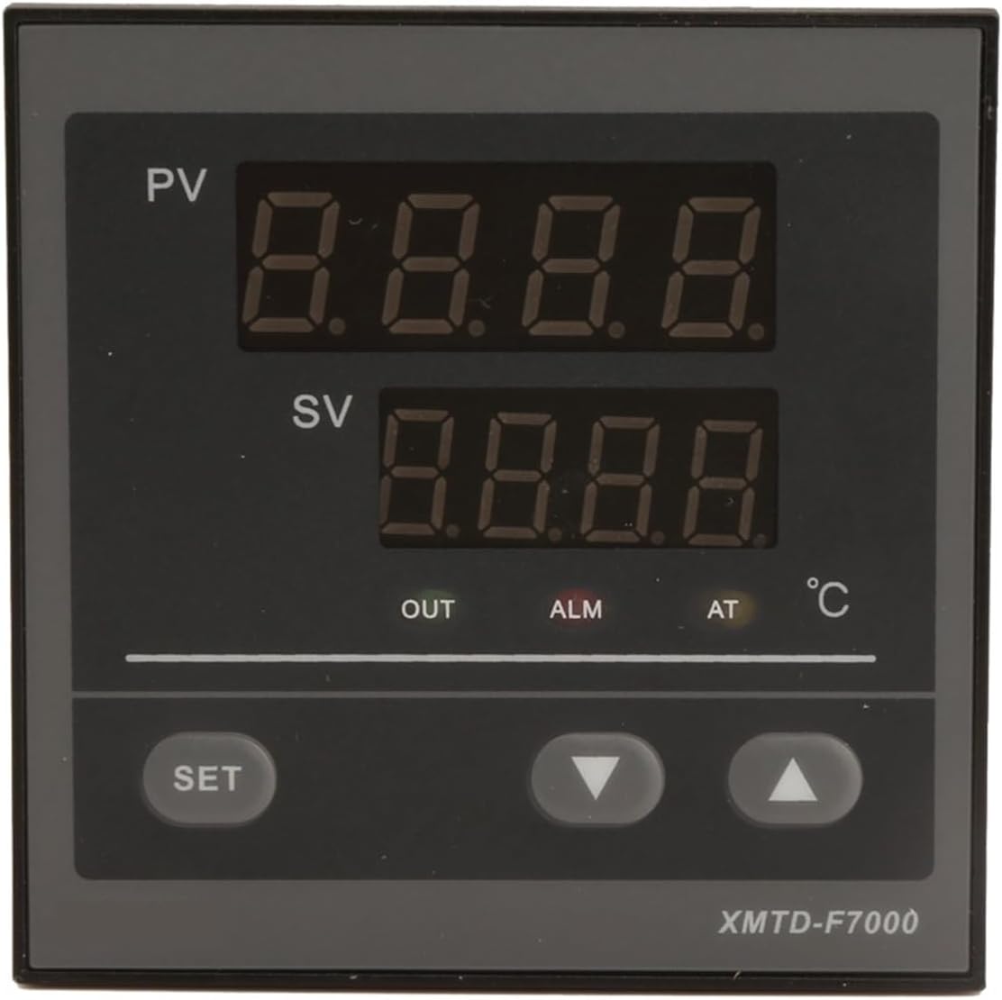
Figure 3.2: Side and Back Panel Overview
Aquest angle view shows the side and a portion of the back panel, highlighting the model number (XMTD-7111, indicating a specific variant or component), voltage, output, and supply specifications. Ventilation slots are visible on the top and sides.

Figure 3.3: Rear Wiring Terminals
La part posterior view illustrates the screw terminals for electrical connections. These terminals are used for power input, sensor input (K, J, E, S type thermocouples), and control outputs (relay and SSR).
3.1. Front Panel Indicators and Buttons
- Visualització de PV (valor de procés): Mostra la temperatura mesurada actual.
- Pantalla SV (valor establert): Shows the target temperature set by the user.
- Indicador OUT: Illuminates when the control output is active.
- Indicador ALM: Illuminates when an alarm condition is met.
- Indicador AT: S'il·lumina quan la funció d'autoajustament està activa.
- Botó SET: S'utilitza per entrar al mode de configuració de paràmetres i confirmar les seleccions.
- Botons amunt / avall: S'utilitza per navegar pels paràmetres i ajustar els valors.
4. Especificacions
| Paràmetre | Valor |
|---|---|
| Precisió | ±1.0% ± 1.0 character; ±0.5% ± 1.0 character (two levels) |
| Coeficient de temperatura | Not more than 0.05%/°C (operating within 0-50°C) |
| Additional Cold End Compensating Error | Not more than ±2°C |
| PID Set Range (P) | 0-100% |
| PID Set Range (I) | 0-4320 segons |
| PID Set Range (D) | 0-1200 segons |
| Phase Style Controller Hysteresis Set Range | At P value |
| Controlling and Alarm Value Set Range | Full scale 0-100% |
| Poder de Treball | AC 100V-240V, 50Hz, Power dissipation ≤3W, or AC240V±10% |
| Temperatura de l'entorn de treball | 0 a 50 °C |
| Ambient de treball Humitat | 30-85% relative humidity (non-corrosive air) |
| Output Contact Volume | CA 250V 3A |
| Senyal d'entrada | K, J, E, S type thermocouples |
| Law of Regulation | Full scale, maximum absolute value alarm |
| Sortida | Sortida de contacte de relé |
| Mida (L × W × H) | 72×72×113 mm |
| Mida del forat | 68+1×68+1mm |
| Pes de l'article | 10.6 unces |
| Muntatge obligatori | No |
| Nombre de peces | 1 |
5. Configuració
5.1. Muntatge
The XMTD-7000 controller is designed for panel mounting. Prepare a cutout in your control panel with the dimensions of 68+1mm by 68+1mm. Insert the controller into the cutout and secure it using the provided mounting brackets.
5.2. Cablatge
Refer to the wiring diagram printed on the side of the controller (as shown in Figure 3.2) and the terminal layout on the back (Figure 3.3). Ensure all connections are secure and correctly matched to your power supply, sensor, and output devices.
- Font d'alimentació: Connect AC 100V-240V, 50Hz to the designated power terminals.
- Entrada del sensor: Connect your K, J, E, or S type thermocouple to the sensor input terminals. Observe polarity for proper operation.
- Connexions de sortida: Connect your heating/cooling element or other controlled device to the relay contact output terminals. The controller also supports SSR control voltage sortida.
Warning: Incorrect wiring can damage the controller or connected equipment. Always verify connections before applying power.
5.3. Engegada inicial
After completing all wiring, apply power to the controller. The PV display will show the current temperature, and the SV display will show the default set temperature. The controller is now ready for operation and parameter configuration.
6. Funcionament
6.1. Setting the Target Temperature (SV)
- Premeu el botó SET el botó una vegada. La pantalla SV començarà a parpellejar.
- Utilitza el Up i Avall arrow buttons to adjust the SV to your desired target temperature.
- Premeu el botó SET button again to confirm the new SV. The display will stop flashing, and the controller will begin to regulate temperature based on the new setting.
6.2. Understanding Display Indicators
- VA (Valor del Procés): Displays the real-time temperature measured by the sensor.
- SV (Valor definit): Displays the user-defined target temperature.
- SORTIDA: Indicates that the control output (e.g., heating element) is currently active.
- ALM: Indicates that an alarm condition has been met (e.g., temperature exceeding limits).
- A: Indicates that the auto-tuning process is currently running.
6.3. Advanced Parameter Settings (PID Control)
The XMTD-7000 allows for advanced configuration of PID control parameters (Proportional, Integral, Derivative) for optimized temperature stability. Accessing and adjusting these parameters typically involves pressing and holding the SET button for several seconds to enter the parameter menu. Refer to the detailed wiring diagram and parameter list on the device for specific navigation and adjustment procedures.
- P (Proportional Band): Range 0-100%. Controls the output power proportional to the difference between PV and SV.
- I (Integral Time): Range 0-4320 seconds. Eliminates steady-state errors (offset) by adjusting output based on the duration and magnitude of the error.
- D (Derivative Time): Range 0-1200 seconds. Responds to the rate of change of the error, helping to prevent overshoot and undershoot.
Note: Adjusting PID parameters requires an understanding of control theory. Incorrect settings can lead to unstable temperature control. It is recommended to use the auto-tuning function or consult an expert if you are unfamiliar with PID tuning.
6.4. Auto-Tuning Function
The auto-tuning function automatically calculates optimal PID parameters for your specific system. To initiate auto-tuning, typically press and hold the SET button until the AT indicator starts flashing. The controller will cycle the output to determine the system's characteristics. Once complete, the AT indicator will turn off, and the new PID parameters will be saved.
7. Manteniment
7.1. Neteja
Keep the controller's front panel clean. Use a soft, dry cloth to wipe away dust. For stubborn dirt, a slightly damp Es pot fer servir un drap amb detergent suau, assegurant-vos que no entri líquid al dispositiu. No utilitzeu productes de neteja abrasius ni dissolvents.
7.2. Condicions ambientals
To ensure long-term reliability, operate the controller within the specified environmental conditions: temperature 0 to 50°C and relative humidity 30-85% (non-condensing, non-corrosive air). Avoid installing the unit near heat sources or in areas with excessive vibration.
8. Solució De Problemes
| Problema | Causa possible | Solució |
|---|---|---|
| No display after power-up | Sense subministrament d'alimentació; cablejat incorrecte; font d'alimentació defectuosa. | Comproveu les connexions d'alimentació i el volumtage. Verify wiring according to the diagram. Test power source. |
| La pantalla PV mostra "HHHH" o "LLLL" | Sensor open circuit (HHHH) or short circuit/reverse connection (LLLL); sensor out of range. | Check sensor wiring and connections. Ensure correct sensor type is used. Replace faulty sensor. |
| Temperature unstable or oscillating | Incorrect PID parameters; sensor not properly installed; external disturbances. | Run auto-tuning. Verify sensor placement. Check for drafts or rapid temperature changes in the environment. |
| Output (OUT) indicator not activating | SV is equal to or outside the PV range; output device faulty; wiring issue. | Adjust SV. Check the connected output device. Verify output wiring. |
| Alarm (ALM) indicator constantly on | Alarm set points are too close to PV; actual temperature is outside alarm limits. | Review and adjust alarm parameters. Check if the system is operating within expected temperature ranges. |
Si el problema persisteix després d'intentar aquestes solucions, poseu-vos en contacte amb l'atenció al client.
9. Garantia i Suport
9.1. Informació de la garantia
RWRAPS products are manufactured to high-quality standards. This product is covered by a standard manufacturer's warranty against defects in materials and workmanship. Please retain your proof of purchase for warranty claims. Specific warranty duration and terms may vary; refer to your purchase documentation for details.
9.2. Atenció al client
For technical assistance, troubleshooting beyond this manual, or warranty inquiries, please contact RWRAPS customer support through the retailer where the product was purchased or visit the official RWRAPS weblloc per obtenir informació de contacte.


