
LLS LM-100-24-U2D2
LLS Intelligent LED Driver (Constant Voltage) LM-100-24-U2D2 DALI-2 User Manual
Model: LM-100-24-U2D2 | Brand: LLS
1. Introducció
This manual provides comprehensive instructions for the installation, operation, and maintenance of the LLS LM-100-24-U2D2 Intelligent LED Driver. This constant voltage LED driver is designed for adapting the color temperature of lighting atmospheres, offering a full range of lighting temperatures from cool blue to warm yellow. It features DALI-2 DT8 tunable white capabilities for optimal control over white tones and supports a maximum power output of 100W.
Les característiques clau inclouen:
- Compact and lightweight design with V0 flame-retardant PC materials.
- Clamshell design with screwless strain-relief and dismountable end cap for adjustable housing length.
- Constant power program design ensures consistent brightness during color temperature adjustments.
- Soft-on and fade-in dimming function for enhanced visual comfort.
- Dimming range from 0% to 100%, down to 0.1%.
- Nivell d'exempció d'alta freqüència.

Figure 1: LLS LM-100-24-U2D2 Intelligent LED Driver. This image shows the compact, rectangular white casing of the LED driver with various labels and connection points visible on its surface.
2. Configuració i instal·lació
2.1. Instal·lació física
The LM-100-24-U2D2 driver features a clamshell design with screwless strain-relief. The dismountable end cap allows for adjustment of the housing length as needed. Ensure the driver is installed in a suitable environment, protected from moisture and extreme temperatures.

Figure 2: Protective Housing Application and Removal. This diagram illustrates how to secure the tension plate to fix electric wires, push the side plate outwards to remove the tension plate, and pull the housing left and right from the bottom to remove it for wiring access.
- Cablejat segur: Push the tension plate down to firmly fix the electric wires.
- Access Housing: To open the housing, push the side plate outwards and simultaneously remove the tension plate by prying it up with a tool.
- Remove Housing: Pull the housing left and right from the bottom to fully remove it for internal access.
2.2. Esquema de cablejat
Proper wiring is crucial for safe and correct operation. Always ensure power is disconnected before performing any wiring. The driver supports both DALI connection and Push DIM/CCT connection.

Figure 3: DALI and Push DIM/CCT Wiring Diagrams. This image displays two main wiring configurations: one for DALI connection showing N, L, DALI, and LED outputs, and another for Push DIM/CCT connection detailing N, L, Push DIM, Push CCT, and LED outputs. Wire diameters and strip lengths are specified for each connection type.
2.2.1. DALI Connection
- Connect the AC input (N, L) to the driver.
- Connect the DALI control lines to the DALI terminals.
- Connect the LED output (CCT: 2700-6500K) to the LED fixture.
- Ensure wire diameter is 0.75-1.5 mm² and strip length is 8-9mm for input/DALI.
- Ensure wire diameter is 1.5-2.5 mm² and strip length is 6-7mm for LED output.
2.2.2. Push DIM/CCT Connection
- Connect the AC input (N, L) to the driver.
- Connect the Push DIM and Push CCT control lines.
- Connect the LED output (DIM: 0-100% dimming range, CCT: 2700-6500K) to the LED fixture.
- Push DIM is invalid under DC voltage entrada.
- Dimming interface priority: DALI first, then Push DIM/CCT.
- Ensure wire diameter is 0.75-1.5 mm² and strip length is 8-9mm for input/Push controls.
- Ensure wire diameter is 1.5-2.5 mm² and strip length is 6-7mm for LED output.
Important: The driver is a constant power device. When ordering, ensure the constant power LED fixture is 100W. For example, a 100W driver can connect to 100W x 2CH LED strip, but the total power of the 2 channels will be kept within 100W.
3. Instruccions de funcionament
The LM-100-24-U2D2 LED driver offers flexible control options for dimming and color temperature adjustment, primarily through DALI-2 or Push DIM/CCT interfaces.
3.1. Push DIM/CCT Control
When using a Push DIM/CCT switch, the following operations are available:
- DIM (Brightness Control):
- Control d'encesa/apagada: Short press the DIM switch.
- Atenuació continuada: Long press the DIM switch.
- Ajust de brillantor: With every other long press, the brightness level will adjust in the opposite direction.
- Funció de memòria: The driver remembers the last brightness level adjusted when lights are turned on.
- CCT (Color Temperature Control):
- Ajust de temperatura de color: Long press the CCT switch.
- Ajust direccional: With every other long press, color temperature will adjust in the opposite direction.
- Funció de memòria: The driver remembers the last color temperature adjusted when lights are turned on.
Figure 4: Push DIM/CCT Switch Operation. This section of the image illustrates the functions of a Push DIM/CCT switch, detailing short press for on/off, long press for stepless dimming and color temperature adjustment, and memory functions for both brightness and color temperature.
3.2. DALI-2 Control
The LM-100-24-U2D2 is compatible with DALI-2 control systems, allowing for advanced control over dimming and tunable white (DT8) functionalities. Refer to your DALI-2 control system's manual for specific programming and operation details.
4. Manteniment
The LM-100-24-U2D2 LED driver is designed for reliable operation with minimal maintenance. However, periodic checks and proper handling are recommended.
4.1. Atenció general
- Keep the driver clean and free from dust accumulation.
- Assegureu-vos que hi hagi una ventilació adequada al voltant del conductor per evitar el sobreescalfament.
- Avoid exposing the driver to direct sunlight, high humidity, or corrosive environments.
4.2. Housing Removal for Access
If internal access is required for inspection or wiring adjustments, follow the steps outlined in Section 2.1 for safe housing removal. Always disconnect power before opening the unit.
5. Troubleshooting and Safety Precautions
This section provides general precautions and advice for addressing common issues.
5.1. Consideracions importants
- Instal·lació professional: Products should be installed by qualified professionals.
- Ús exterior: For outdoor installations, ensure the unit is mounted in a waterproof enclosure.
- Compatibilitat: Use only with compatible LED fixtures and wiring. Refer to product parameters.
- Integritat del cablejat: The diameter of wire used must be able to load the light fixtures you connect and ensure firm wiring.
- Protecció de sobrecàrrega: Do not overload the driver. Overloading can cause damage to light fixtures.
- Reparacions: Do not attempt to fix the product yourself. If you have questions or issues, contact your supplier.
Aquest manual està subjecte a canvis sense previ avís. Les funcions del producte depenen de la mercaderia. Si teniu cap pregunta, no dubteu a contactar amb els nostres distribuïdors oficials.
6. Especificacions
Detailed technical specifications for the LM-100-24-U2D2 LED Driver are provided below.

Figure 5: Technical Specifications. This image presents a detailed table of technical parameters for the LM-100-24-U2D2 LED driver, including output, input, environment, protection, EMC, and other general specifications.
6.1. General Technical Data
| Categoria | Paràmetre | Valor | ||
|---|---|---|---|---|
| Sortida | Vol. De sortidatage | 24VDC | ||
| Corrent de sortida | Màx. 4.17A | |||
| Potència de sortida | 100W màx | |||
| Rang de potència de sortida | 0-100W | |||
| Nivell estroboscópico | Nivell d'exempció d'alta freqüència | |||
| Entrada | Freqüència PWM | 3600 Hz | ||
| Rang de regulació | 0-100%, fins a 0.1% | |||
| Limitació de potència de sobrecàrrega | ≤102% | |||
| Onda i soroll | Switch ripples≤150mV, noise≤500mV | |||
| Interfície d'atenuació | DALI-2 DT8, Push DIM/CCT | |||
| Entrada Voltage | 120-277VAC | |||
| Freqüència | 50/60Hz | |||
| Corrent d'entrada | 0.85A/120Vac, 0.55A/230Vac, 0.45A/277Vac | |||
| Factor de potència | PF>0.99/120Vac, PF>0.95/230Vac, PF>0.9/277Vac (at full load) | |||
| THD | 120Vac@THD <5%, 230Vac@THD <8%, 277Vac@THD <11% (at full load) | |||
| Medi ambient | Eficiència (Tipus) | 92% | ||
| Pèrdua d'energia en espera | ≤0.5 W | |||
| Corrent d'entrada | Cold start 45A/230Vac (Test width = 860us under 50% Ipeak) | |||
| Corrent de fuga | Màx. 0.5 mA | |||
| Temperatura de treball | Ta: -20~50°C Tc: 85°C | |||
| Protecció | Humitat de treball | 20 ~ 95% HR, sense condensació | ||
| Temperatura/humitat d'emmagatzematge | -40~80°C, 10-95% HR | |||
| Coeficient de temperatura | ±0.03%/°C (0-50°C) | |||
| Vibració | 10-500Hz, 2G 10min/1cycle, 72 min for X, Y and Z axes respectively | |||
| Més del voltage Protecció | Shut down and auto-restart or turn off the output current if the PCB temperature >110°C, and recover automatically | |||
| Protecció de sobrecàrrega | Apagueu la sortida quan no hi hagi càrregatage>28V, and recover automatically | |||
| EMC | Protecció de sobretemperatura | Shut down the output when output current load>102%, and recover automatically | ||
| Protecció contra curtcircuits | Enter hiccup mode in case of short circuit, and recover automatically | |||
| Resistir voltage | I/PO/P: 3750 VCA | |||
| Altres | Resistència d'aïllament | I/PO/P: 100MΩ/500VDC/25°C/70%RH | ||
| Normes de seguretat | UL | UL8750 | ||
| CUL | Canadà | CSA C22.2 NÚM. 250.13 | ||
| CE | Unió Europea | EN61347-1, EN61347-2-13, EN62384 | ||
| Emissió EMC | CE | Unió Europea | EN55015 | |
| Immunitat EMC | CE | Unió Europea | EN61000-3-2, EN61000-3-3, EN61547 | |
| Dimensions | Dimensions del producte | 352 x 44 x 33mm (13.86 x 1.73 x 1.30 polzades) | ||
| Pes brut (GW) | 430 g | |||
| Mida del cartró | 392x270x230mm, 9.4kg/5pcs/ctn | |||
| Número de model | LM-100-24-U2D2 |
6.2. Característiques de rendiment
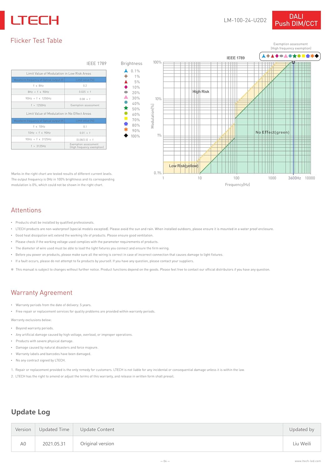
Figure 6: Performance Graphs and Flicker Test. This image displays several graphs including Efficiency vs Load, Power Factor Characteristic, THD vs Load, and Over Load Diagram, illustrating the driver's performance under various conditions. It also includes a Flicker Test Table and a Flicker Test Chart based on IEEE 1789 standards.
6.2.1. Flicker Test Table (IEEE 1789)
| Valor límit de modulació en zones de baix risc | Valor límit de modulació en zones sense efecte |
|---|---|
| f < 90Hz: 0.025 x f | f < 1250Hz: 0.08 x f |
| f ≥ 1250Hz: 1 | f ≥ 1250Hz: 1 |
The output frequency is 0Hz in 100% brightness, and its corresponding modulation is 0%, which is not shown in the chart.
7. Warranty Agreement
This product is covered by a warranty agreement provided by LTECH. Please review the terms below.
- Període de garantia: 5 anys des de la data de lliurament.
- Garantia de qualitat: Free repair or replacement for quality problems within the warranty period.
7.1. Exclusions de garantia
La garantia no cobreix:
- Més enllà del període de garantia especificat.
- Damage caused by high voltage, sobrecàrrega o operacions inadequades.
- Damage due to physical impact.
- Danys causats per catàstrofes naturals i força major.
- Damage to warranty labels or barcodes.
- Danys causats per un desmuntatge no autoritzat.
Repair or replacement is the sole remedy for customers. LTECH is not liable for any incidental or consequential damage unless it is within the law. LTECH reserves the right to amend or adjust the terms of this warranty, and release in written form shall prevail.
8. Suport i contacte
For any questions, technical assistance, or warranty claims, please contact your supplier or an authorized LLS distributor. Do not attempt to repair the product yourself, as this may void the warranty and pose safety risks.
8.1. Update Log
| Versió | Hora actualitzada | Actualitzar contingut | Actualitzat per |
|---|---|---|---|
| A0 | 2021.05.31 | Versió original | Liu Weili |
Ask a question about this manual
Ask about setup, troubleshooting, compatibility, parts, safety, or missing instructions. Manuals+ will review the question and use this page’s manual context to help answer it.