
1. Introducció
This manual provides detailed instructions for the installation, operation, and maintenance of your EPEVER Tracer2210AN-G3 20A MPPT Solar Charge Controller. This device is designed to efficiently manage power flow from solar panels to various battery types, including lead-acid and lithium batteries.
Les característiques clau inclouen:
- Tecnologia MPPT avançada amb una eficiència no inferior al 99.5%.
- Automatic 12V/24V system voltage reconeixement.
- Volum màxim d'entrada PVtage de 100V.
- Support for Gel, AGM, Flooded, Sealed, and Lithium (LiFePO4, Li(NiCoMn)O2) batteries.
- Disseny comú de connexió a terra negativa.
- RS-485 communication bus interface with Modbus protocol for monitoring and parameter setting via mobile app or PC software.
- Funció de limitació de potència de càrrega i corrent.
- Real-time energy statistics function and overheating power reduction.

Figure 1.1: EPEVER Tracer2210AN-G3 20A MPPT Solar Charge Controller with LCD display.
2. Configuració i instal·lació
Proper installation is crucial for optimal performance and safety. Follow the connection order carefully.
2.1 Connection Order
Connect the system components in the following sequence:
- Bateria: Connecteu la bateria al controlador de càrrega.
- PV Panel: Connect the solar PV panel to the charge controller.
- Càrrega: Connect the DC load to the charge controller.
To disconnect the system, reverse the order: Load → PV Panel → Battery.

Figure 2.1: Diagram illustrating the correct connection order for the solar charge controller, battery, PV panel, and DC load.
2.2 No-Battery Mode and Battery Mode
The Tracer-AN G3 series supports operation with or without a battery, depending on the inverter type and power requirements.

Figure 2.2: Connection diagrams for operating the solar charge controller in no-battery mode (top) and battery mode (bottom).
No-Battery Mode Warning: When operating without a battery, ensure the inverter is connected directly to the controller's battery terminals. For high-frequency inverters, PV input power must be greater than (load output power ÷ inverter conversion efficiency ÷ controller conversion efficiency). For power frequency inverters, PV input power must be greater than (load output power ÷ inverter conversion efficiency ÷ controller conversion efficiency ÷ 2).
2.3 Temperature Sensor Connection
Connect the remote temperature sensor probe to the designated port on the controller. This ensures accurate temperature compensation for charging parameters, optimizing battery life.
Video 2.1: Demonstrates the unboxing, overview of components, and basic installation steps for the Tracer-AN controller, including connecting the temperature sensor.
3. Instruccions de funcionament
The controller features an LCD display and buttons for easy configuration and monitoring.
3.1 Configuració del tipus de bateria
To ensure proper charging, configure the battery type on the controller:
- Press and hold the "ENTER" button for 5 seconds under the battery voltage interfície.
- Press the "SELECT" button when the battery type interface is flashing to cycle through available types.
- Press the "ENTER" button to confirm the selected battery type.

Figure 3.1: LCD display showing battery type selection options.
Tipus de bateries compatibles:
- Lead-acid: Sealed (default), Gel, Flooded, User-defined.
- Liti: LiFePO4 (4s/8s), Li(NiCoMn)O2 (3s/6s/7s), User-defined.
3.2 Setting Load Mode
The controller offers multiple load working modes. To set the load mode:
- Press and hold the "ENTER" button for 5 seconds under the load mode interface.
- Press the "SELECT" button when the load mode interface is flashing to cycle through options.
- Press the "ENTER" button to confirm the desired load mode.
Mode de control manual: When you press the ENTER button, the load will open; press ENTER again, the load will close.
3.3 Modes de treball de càrrega
| 1** | Temporitzador 1 | 2** | Temporitzador 2 |
|---|---|---|---|
| 100 | Llum ON/OFF | 2n | Inhabilitat |
| 101 | La càrrega estarà activada durant 1 hora des de la posta de sol | 201 | La càrrega estarà activada 1 hora abans de la sortida del sol |
| 102 | La càrrega estarà activada durant 2 hores des de la posta de sol | 202 | La càrrega estarà activada durant 2 hores abans de la sortida del sol |
| 103-113 | Load will be on for 3 ~ 13 hours since sunset | 203-213 | La càrrega estarà activada entre 3 i 13 hores abans de la sortida del sol |
| 114 | La càrrega estarà activada durant 14 hores des de la posta de sol | 204 | La càrrega estarà activada durant 14 hores abans de la sortida del sol |
| 115 | La càrrega estarà activada durant 15 hores des de la posta de sol | 205 | La càrrega estarà activada durant 15 hores abans de la sortida del sol |
| 116 | Mode de prova | 2n | Inhabilitat |
| 117 | Mode manual (càrrega predeterminada activada) | Inhabilitat |
4. Accessoris
The EPEVER Tracer2210AN-G3 controller supports various accessories for enhanced monitoring and control:
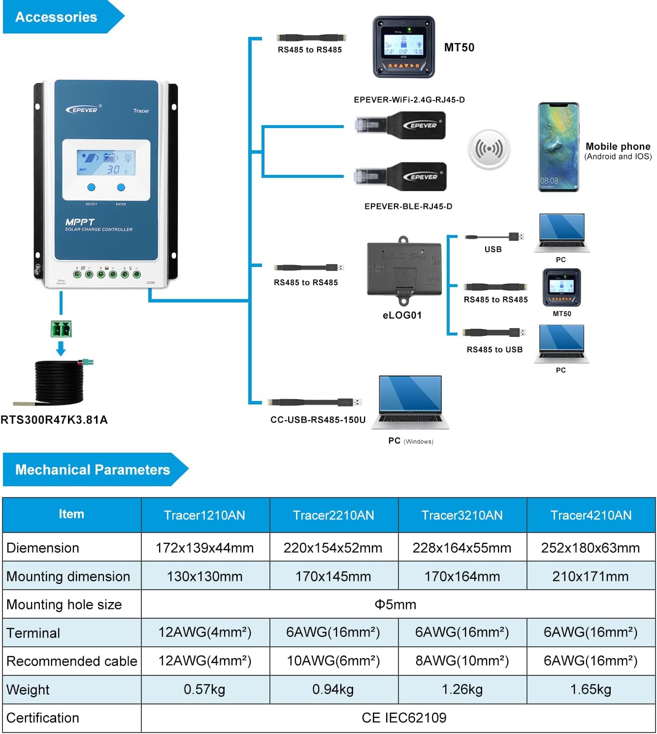
Figure 4.1: Diagram showing the EPEVER Tracer2210AN-G3 controller and compatible accessories.
- Remote Temperature Sensor (RTS300R47K3.81A): Acquires battery temperature for compensation of control parameters. Standard cable length is 3m.
- USB to RS485 Cable (CC-USB-RS485-150U): Used to monitor and set parameters via PC software (Solar Station PC software). Cable length is 1.5m.
- Remote Meter (MT50): Displays various operating data and system faults. Features easy-to-operate buttons and a numeric display.
- WiFi Serial Adapter (eBox-WiFi-01): For monitoring and setting parameters via mobile APP software through WiFi signals.
- RS485 to Bluetooth Adapter (eBox-BLE-01): For monitoring and setting parameters via mobile APP software through Bluetooth signals.
- Logger (eLOG01): Records real-time operating status of the controller.
Vídeo 4.1: Un overview of the EPEVER G3 Version TracerAN MPPT Solar Charge Controller, highlighting its features and accessories.
5. Especificacions
5.1 Paràmetres mecànics
| Item | Tracer1210AN | Tracer2210AN | Tracer3210AN | Tracer4210AN |
|---|---|---|---|---|
| Dimensió | 172x139x44 mm | 220x154x52 mm | 228x164x55 mm | 252x180x63 mm |
| Dimensió de muntatge | 130x130mm | 170x145mm | 170x164mm | 210x171mm |
| Mida del forat de muntatge | Φ5 mm | |||
| Terminal | 12AWG (4 mm²) | 6AWG (16 mm²) | 6AWG (16 mm²) | 6AWG (16 mm²) |
| Cable recomanat | 12AWG (4 mm²) | 10AWG (6 mm²) | 8AWG (10 mm²) | 6AWG (16 mm²) |
| Pes | 0.57 kg | 0.94 kg | 1.26 kg | 1.65 kg |
| Certificació | CE IEC62109 | |||
5.2 Electrical Parameters (Tracer2210AN)
| Item | Tracer 1210AN | Tracer 2210AN | Tracer 3210AN | Tracer 4210AN |
|---|---|---|---|---|
| Vol nominal del sistematage | 12 / 24VDC automàtic | |||
| Corrent de càrrega nominal | 10A | 20A | 30A | 40A |
| Corrent nominal de descàrrega | 10A | 20A | 30A | 40A |
| Bateria voltage gamma | 8~32V | |||
| Màx. Circuit obert fotovoltaic voltage | 100 V1. | 92 V2. | ||
| MPP voltage gamma | (Bateria voltage +2V)~72V | |||
| Màx. Potència d'entrada fotovoltaica | 130W/12V 260W/24V | 260W/12V 520W/24V | 390W/12V 780W/24V | 520W/12V 1040W/24V |
| Autoconsum | ≤12mA | |||
| Circuit de descàrrega voltage gota | ≤0.23V | |||
| Coeficient de compensació de temperatura3 | -3mV/℃/2V (per defecte) | |||
| Posada a terra | Negatiu comú | |||
| Interfície RS485 | 5VDC / 100mA | |||
| Temps de llum de fons LCD | 60S (per defecte) | |||
| Temperatura ambient de treball④ | -25℃~+50℃ (100% input and output) | |||
| Interval de temperatura d'emmagatzematge | -20 ℃ ~ + 70 ℃ | |||
| Humitat relativa | ≤95%, NC | |||
| Tancament | IP30 | |||
1.When a lead-acid battery is used, the controller hasn't the low temperature protection.
2.A la temperatura ambiental mínima de funcionament
3A una temperatura ambiental de 25 ℃
④When a lithium-ion battery is used, the system voltage can't be identified automatically.
6. Manteniment
To ensure the longevity and optimal performance of your EPEVER Tracer2210AN-G3 MPPT Solar Charge Controller, regular maintenance is recommended. Please refer to the full product manual for detailed maintenance procedures. Key maintenance aspects typically include:
- Periodically inspect all wiring and connections for tightness and corrosion.
- Ensure the controller's heat sink is free from dust and debris to maintain proper cooling.
- Verify that the ventilation around the controller is unobstructed.
- Check the battery terminals for any signs of wear or damage.
- Monitor the system's performance regularly via the LCD display or connected monitoring software/app to detect any anomalies.
7. Solució De Problemes
If you encounter any issues with your EPEVER Tracer2210AN-G3 MPPT Solar Charge Controller, please refer to the comprehensive troubleshooting guide in the full product manual. Common issues and their solutions are typically covered, including:
- LCD display not lighting up or showing incorrect readings.
- Battery not charging or overcharging.
- Load not functioning correctly.
- Error codes or warning indicators on the display.
For complex issues or if problems persist, please contact customer support.
8. Garantia i Suport
EPEVER products are backed by a manufacturer's warranty. For specific warranty terms and conditions, please refer to the warranty card included with your product or contact the seller.
Authorized Supplier: GolandCentury is an authorized supplier for the EPEVER brand. Our engineers are available to provide technical support and assistance with your solar system setup.
For technical inquiries or support, please reach out to GolandCentury's service centers.