
1. Introducció
The GODIYMODULES TCS230/TCS3200 Color Sensor Detector Module is a versatile device designed for color recognition applications. It integrates a TCS3200 color sensor chip, which converts light intensity into a proportional output frequency. This module is suitable for use with various microcontrollers, including Arduino, enabling projects that require color detection capabilities.
Les característiques principals d'aquest mòdul inclouen:
- Integrated TCS3200 chip for reliable color sensing.
- Vol d’entradatagrang de DC 3V a 5V.
- Freqüència de sortida voltagrang de 0V a 5V.
- Direct connectivity with microcontrollers.
- Optimal detection distance of approximately 10mm for static object color detection.
- Compact size for easy integration into projects.

Figura 1: superior view of the TCS230/TCS3200 Color Sensor Module, showing the sensor array and illuminating LEDs.
2. Configuració i connexions
Proper connection of the TCS230/TCS3200 module to your microcontroller is crucial for correct operation. The module operates on a 3V to 5V DC power supply.
2.1 Descripció del pinout
The module features several pins for power, control, and output. Refer to the table below for a detailed pin description:
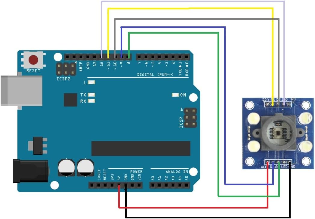
Figure 2: Pinout diagram and table for the TCS230/TCS3200 Color Sensor Module.
| Pin núm. | Nom del pin | Descripció |
|---|---|---|
| 4 | GND | Power supply ground. All voltages are referenced to this pin. |
| 5 | VCC | Subministrament voltage (DC 3V-5V). |
| 3 | OE | Output Enable (Active low). Connect to GND to enable output. |
| 6 | FORA | Output frequency (fO). This pin provides the square wave output. |
| 1, 2 | S0, S1 | Select lines for output frequency scaling. |
| 7, 8 | S2, S3 | Select lines for photodiode type (color filter selection). |
Ex. 2.2ample Wiring with Arduino
Below is a typical wiring diagram for connecting the TCS230/TCS3200 module to an Arduino board. Ensure all connections are secure before applying power.

Figura 3: Example wiring of the color sensor module to an Arduino Uno board.
- VCC to Arduino 5V
- GND to Arduino GND
- FORA to Arduino Digital Pin (e.g., Pin 8)
- S0 to Arduino Digital Pin (e.g., Pin 2)
- S1 to Arduino Digital Pin (e.g., Pin 3)
- S2 to Arduino Digital Pin (e.g., Pin 4)
- S3 to Arduino Digital Pin (e.g., Pin 5)
- OE to GND (to enable output) or to an Arduino Digital Pin for software control.
3. Instruccions de funcionament
The TCS230/TCS3200 module operates by selecting specific color filters (Red, Green, Blue, or Clear) and a frequency scaling factor. The sensor then outputs a square wave whose frequency is directly proportional to the intensity of the detected light.
3.1 Frequency Scaling (S0, S1)
The S0 and S1 pins control the output frequency scaling. This allows for adjusting the output frequency range to suit different microcontroller input capabilities or measurement resolutions.
| S0 | S1 | Output Frequency Scaling |
|---|---|---|
| BAIXA | BAIXA | Apagada |
| BAIXA | ALTA | 2% |
| ALTA | BAIXA | 20% |
| ALTA | ALTA | 100% |
3.2 Color Filter Selection (S2, S3)
The S2 and S3 pins control which color filter (red, green, blue, or clear) is active, allowing the sensor to measure the intensity of specific color components.
| S2 | S3 | Photodiode Type |
|---|---|---|
| BAIXA | BAIXA | Filtre vermell |
| BAIXA | ALTA | Filtre blau |
| ALTA | BAIXA | Clear (no filter) |
| ALTA | ALTA | Filtre verd |
3.3 Procediment de mesura
- Set the desired output frequency scaling using S0 and S1.
- Select the color filter (Red, Green, Blue, or Clear) using S2 and S3.
- Position the object to be measured approximately 10mm from the sensor for optimal results.
- Read the frequency output from the OUT pin using your microcontroller's interrupt or pulse-counting capabilities.
- Repeat for other color filters to obtain RGB values.
4. Manteniment
The TCS230/TCS3200 Color Sensor Detector Module is a robust electronic component, but proper care ensures its longevity and accurate performance.
- Mantenir net: Regularly clean the sensor's optical window with a soft, dry, lint-free cloth to prevent dust or smudges from affecting readings. Avoid abrasive materials or harsh chemicals.
- Eviteu la humitat: Protect the module from water and high humidity, which can damage electronic components.
- Manejar amb cura: Avoid dropping the module or subjecting it to excessive mechanical stress. Static electricity can also damage sensitive components; use anti-static precautions when handling.
- Emmagatzematge: Guardeu el mòdul en un lloc sec i fresc, allunyat de la llum solar directa i de temperatures extremes.
5. Solució De Problemes
If you encounter issues with your TCS230/TCS3200 module, consider the following troubleshooting steps:
- No Output Frequency:
- Verify power connections (VCC and GND) are correct and within the 3V-5V range.
- Ensure the OE (Output Enable) pin is connected to GND or driven LOW by your microcontroller.
- Check all wiring for continuity and correct pin assignments.
- Confirm that S0 and S1 are not set to 'Power Down' mode (LOW, LOW).
- Lectures incorrectes o inestables:
- Condicions d'il·luminació: Ensure consistent and adequate lighting on the object. Ambient light can interfere with readings; consider using the onboard LEDs or a controlled light source.
- Distància de detecció: Maintain the optimal detection distance of approximately 10mm. Too close or too far can affect accuracy.
- Neteja del sensor: Clean the sensor's optical window as described in the Maintenance section.
- Frequency Scaling: Experiment with different frequency scaling settings (S0, S1) to find the best range for your application.
- Code Logic: Review your microcontroller code to ensure correct reading of the frequency and proper interpretation of color values.
- Module Not Recognized by Microcontroller:
- Double-check all digital pin connections for S0, S1, S2, S3, and OUT.
- Ensure your microcontroller's pins are configured correctly as inputs/outputs.
6. Especificacions
Detailed technical specifications for the TCS230/TCS3200 Color Sensor Detector Module:
- Xip: TCS3200
- Entrada Voltage: CC 3V ~ 5V
- Output Frequency Voltage: 0V ~ 5V
- Optimal Detection Distance: 10 mm
- Module Dimensions (approx): 3.3 cm x 3.3 cm x 2.5 cm (1.3 polzades x 1.3 polzades x 0.98 polzades)
- Item Weight (approx): 0.704 unces (20 grams)
- Package Dimensions (approx): 3.94 x 1.97 x 0.39 polzades (10 cm x 5 cm x 1 cm)
7. Garantia i Suport
For specific warranty information regarding your GODIYMODULES TCS230/TCS3200 Color Sensor Detector Module, please refer to the retailer's website or contact the point of purchase. Warranty terms may vary depending on the seller and region.
For technical support, detailed datasheets, example code, or community forums related to the TCS230/TCS3200 sensor, it is recommended to consult online resources for the TCS3200 chip or relevant microcontroller platforms (e.g., Arduino forums). You may also contact the retailer for assistance.