1. Introducció
The Velleman DVM810 is a compact and economical 3 1/2 digit digital multimeter designed for measuring DC and AC voltages, DC currents, resistance, and for performing diode and transistor (hFE) tests. It features overload protection and automatic polarity indication, making it suitable for hobbyists, field use, and workshops. This manual provides essential information for the safe and effective operation of your DVM810 multimeter.
2. Característiques del producte
- Automatic polarity indication
- Voltage measurements: AC 500V and DC 500V maximum
- Current measurements: DC 10A maximum (0.2A fused, 10A unfused)
- Resistance measurements: Up to 2MΩ
- Diode and transistor (hFE) test functions
- Protecció de sobrecàrrega
- Compact design with 3 1/2 digit LCD display
3. Contingut del paquet
Si us plau, comproveu el contingut del paquet per assegurar-vos que hi hagi tots els elements:
- Multímetre digital Velleman DVM810
- Cables de prova (un vermell, un negre)
- Manual d'instruccions
4. Informació important de seguretat
Read all safety warnings and instructions carefully before using this product. Failure to follow these instructions may result in electric shock, fire, or serious injury.
- Always ensure the multimeter is set to the correct function and range before making any measurements.
- Never exceed the maximum input limits for any range. The maximum voltage for AC/DC is 500V.
- No intenteu mesurar el corrent en circuits amb volumtagés superior a 250V.
- Inspect test leads for damaged insulation or exposed metal before each use. Replace damaged leads immediately.
- No feu servir el multímetre si sembla que està danyat o si la carcassa està oberta.
- Exercise extreme caution when working with live circuits. Use appropriate personal protective equipment.
- Desconnecteu sempre l'alimentació del circuit i descarregueu l'energia d'alt volum.tage capacitors before measuring resistance or performing diode/transistor tests.
- Replace the battery when the low battery indicator appears on the display to ensure accurate readings.
5. Producte acabatview
Familiarize yourself with the components of your Velleman DVM810 multimeter:
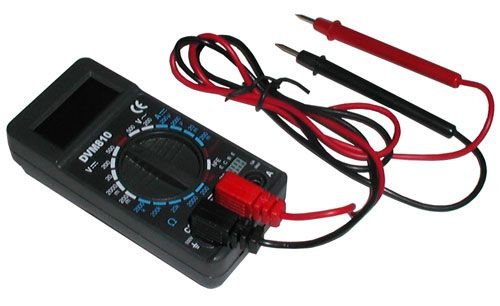
Figure 1: Velleman DVM810 Digital Multimeter. This image displays the front view of the compact multimeter, highlighting its liquid crystal display (LCD), the central rotary function switch, and the input jacks for test leads at the bottom.
- Pantalla LCD: Shows measurement readings, units, and polarity.
- Interruptor rotatiu: Used to select the desired measurement function and range.
- Preses d'entrada:
- COM Jack: Common (negative) input for all measurements. Connect the black test lead here.
- Presa VΩmA: Entrada positiva per al volumtage, resistance, and current measurements up to 200mA. Connect the red test lead here.
- Jack de 10A: Positive input for high current measurements (up to 10A). Connect the red test lead here for 10A measurements.
- Cables de prova: Red and black leads used to connect the multimeter to the circuit under test.
6. Configuració
6.1 Instal·lació de la bateria
The DVM810 multimeter requires a 9V battery (not always included). To install or replace the battery:
- Ensure the multimeter is turned OFF (rotary switch set to OFF).
- Localitzeu la tapa del compartiment de la bateria a la part posterior de la unitat.
- Remove the screw(s) securing the cover and carefully lift it off.
- Connect a new 9V battery to the battery clip, observing correct polarity.
- Col·loqueu la bateria al compartiment i torneu a col·locar la tapa, fixant-la amb el(s) cargol(s).
6.2 Connexió dels cables de prova
Always connect the test leads correctly for accurate and safe measurements:
- Introduïu el cable de prova negre al COM (common) jack.
- Per a la majoria de mesures (voltage, resistance, diode, hFE, and current up to 200mA), insert the red test lead into the VΩmA jack.
- Per a mesures de corrent elevat (fins a 10 A), inseriu el cable de prova vermell al 10A jack.
7. Instruccions de funcionament
Before making any measurement, ensure the test leads are correctly connected and the rotary switch is set to the appropriate function and range.
7.1 Mesurar DC Voltage (V=)
- Introduïu el cable vermell al VΩmA jack and the black lead into the COM jack.
- Ajusteu l'interruptor rotatiu al volum de CC desitjattage (V=) range. Start with the highest range if the voltage es desconeguda.
- Connect the test leads across the component or circuit to be measured (in parallel).
- Llegeix el voltage value on the LCD display. The display will show the correct polarity.
7.2 Mesurar AC Voltage (V~)
- Introduïu el cable vermell al VΩmA jack and the black lead into the COM jack.
- Ajusteu l'interruptor rotatiu al volum de CA desitjattage (V~) range. Start with the highest range if the voltage es desconeguda.
- Connect the test leads across the component or circuit to be measured (in parallel).
- Llegeix el voltage valor a la pantalla LCD.
7.3 Measuring DC Current (A=)
Caution: Never connect the multimeter in parallel with a voltagla font d'alimentació en mesurar el corrent, ja que això pot fer saltar el fusible o fer malbé el mesurador.
- Determine the expected current. For currents up to 200mA, insert the red lead into the VΩmA jack. For currents up to 10A, insert the red lead into the 10A jack. Always insert the black lead into the COM jack.
- Set the rotary switch to the appropriate DC Current (A=) range. Start with the highest range if the current is unknown.
- Turn off power to the circuit. Open the circuit where the current is to be measured.
- Connecteu el multímetre en sèrie amb el circuit.
- Restore power to the circuit and read the current value on the LCD display.
7.4 Mesura de la resistència (Ω)
Caution: Ensure the circuit is completely de-energized and all capacitors are discharged before measuring resistance.
- Introduïu el cable vermell al VΩmA jack and the black lead into the COM jack.
- Set the rotary switch to the desired Resistance (Ω) range. Start with a higher range if the resistance is unknown.
- Connecteu els cables de prova al component que s'ha de mesurar.
- Llegiu el valor de la resistència a la pantalla LCD.
7.5 Prova de díodes
Caution: Ensure the diode is disconnected from the circuit or the circuit is de-energized before testing.
- Introduïu el cable vermell al VΩmA jack and the black lead into the COM jack.
- Set the rotary switch to the Diode symbol (→|).
- Connecteu el cable vermell a l'ànode i el cable negre al càtode del díode. La pantalla mostrarà el volum directe.tage drop (typically 0.5V to 0.8V for silicon diodes).
- Reverse the leads. The display should show 'OL' (Overload) for a good diode. If it shows a reading in both directions or 'OL' in both directions, the diode may be faulty.
7.6 Transistor (hFE) Test
Caution: Ensure the transistor is disconnected from the circuit before testing.
- Introduïu el cable vermell al VΩmA jack and the black lead into the COM jack.
- Col·loqueu l'interruptor giratori a la posició hFE.
- Identify if the transistor is NPN or PNP. Insert the transistor's emitter, base, and collector leads into the corresponding holes in the hFE socket on the multimeter.
- Read the hFE (DC current gain) value on the LCD display.
8. Especificacions
| Paràmetre | Valor |
|---|---|
| Marca | Velleman |
| Número de model | DVM810 |
| Tipus de mesura | Multímetre |
| DC Voltage Rang | Fins a 500V |
| Vol. ACtage Rang | Fins a 500V |
| Interval de corrent DC | Up to 10A (0.2A fused, 10A unfused) |
| Interval de resistència | Fins a 2 MΩ |
| Prova de díode | Sí |
| Prova de transistors (hFE) | Sí |
| Mostra | 3 1/2 Digit LCD |
| Font d'alimentació | Pila de 9V (no inclosa) |
| Dimensions | Aproximadament 3.70 cm x 1.81 cm x 1.03 cm |
| Pes de l'article | Aproximadament 3.2 unces (0.2 lliures) |
| UPC | 836479002272 |
9. Manteniment
9.1 Substitució de la bateria
When the low battery indicator appears on the LCD, replace the 9V battery as described in Section 6.1. A weak battery can lead to inaccurate readings.
9.2 Neteja
Per netejar el multímetre, netegeu la carcassa amb aiguaamp drap i un detergent suau. No utilitzeu abrasius ni dissolvents. Assegureu-vos que la unitat estigui completament seca abans d'utilitzar-la.
9.3 Inspecció dels cables de prova
Regularly inspect the test leads for any signs of damage, such as cracked insulation, exposed wires, or loose connections. Replace damaged leads immediately to prevent electric shock hazards.
10. Solució De Problemes
- Sense pantalla o pantalla tènue: Comproveu la bateria. Substituïu-la si cal.
- Lectures incorrectes:
- Ensure the rotary switch is set to the correct function and range.
- Comproveu el volum de la bateriatage; replace if low.
- Ensure test leads are properly connected and not damaged.
- For resistance measurements, ensure the circuit is de-energized.
- Es mostra 'OL' (sobrecàrrega): El valor mesurat supera el rang seleccionat. Seleccioneu un rang superior o assegureu-vos que el circuit estigui dins de les capacitats del mesurador.
- Fuse blown (during current measurement): If the meter stops measuring current, the internal fuse may have blown. Refer to a qualified technician for fuse replacement.
11. Garantia i Suport
Warranty information for the Velleman DVM810 Digital Multimeter is typically provided with your purchase documentation or can be found on the official Velleman website. For technical support, service, or further inquiries, please refer to the contact information provided by your retailer or the manufacturer's official support channels.


