1. Introducció
The EPEVER Tracer AN series solar charge controller, including the 100A Tracer 10415AN model, is designed for advanced solar power systems. It features a common negative design and an advanced Maximum Power Point Tracking (MPPT) control algorithm. An integrated LCD displays the operating status, providing real-time system information. This controller is engineered to maximize energy harvest from photovoltaic (PV) arrays by efficiently tracking the maximum power point under various conditions, potentially increasing energy utilization by 10%-30% compared to traditional PWM methods. It incorporates features such as charging power and current limitation, automatic charge reduction at high temperatures, and enhanced communication port protection for improved reliability. The three-stage adaptive charging mode extends battery life and enhances overall system performance, while comprehensive electronic protection functions safeguard system components against installation errors or failures, ensuring safe and reliable long-term operation.
2. Característiques clau
- Tecnologia MPPT avançada: Features ultra-fast tracking speed with a tracking efficiency of no less than 99.5%. The maximum DC/DC transfer efficiency reaches 98.6%, with full load efficiency up to 98%.
- Optimized MPP Tracking: The advanced MPPT control algorithm minimizes MPP loss rate and time, ensuring accurate recognition and tracking of multi-peak MPPs across a wider operating voltage gamma.
- Automatic System Voltage Identificació: Automatically identifies 12V, 24V, 36V, or 48V system voltages. Includes an automatic control system to limit charging power and current if they exceed rated values.
- Versatile Battery Charging: Supports four charging options: sealed, gel, flooded, and user-defined battery types.
- System Expandability: Supports parallel connection of up to 6 units to expand system capacity. Features an external load switch signal control load relay for diversified load working modes.
- Funcions de protecció: Includes automatic over-temperature power reduction and battery temperature compensation functions. Ensures 100% full load operation within the specified working environment temperature range during charging and discharging.
3. Producte acabatview
3.1 Aparença física
The EPEVER Tracer 10415AN MPPT Solar Charge Controller features a robust design with a clear LCD display and control buttons on the front panel. Mounting brackets are integrated on the sides for secure installation.
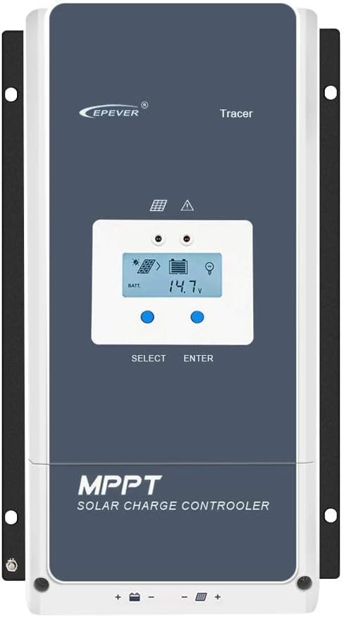
Figura 3.1: Frontal view of the EPEVER Tracer 10415AN MPPT Solar Charge Controller, showing the LCD screen and control buttons.
3.2 Dimensions
Understanding the physical dimensions is crucial for proper installation and space allocation. The controller measures approximately 394mm in length, 242mm in width, and 143mm in height.
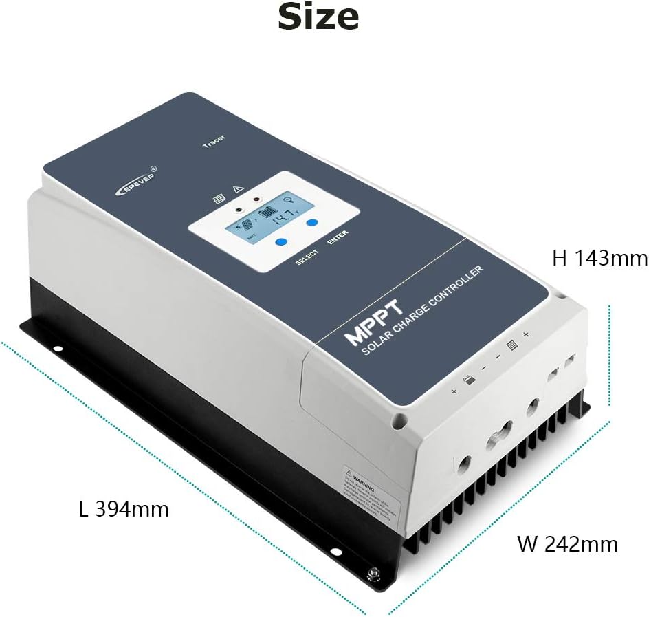
Figure 3.2: Diagram illustrating the length (L 394mm), width (W 242mm), and height (H 143mm) of the solar charge controller.
3.3 Identificació de components
The rear and side panels of the controller house various terminals and ports for system connections and communication. Refer to the diagram and table below for detailed identification.

Figura 3.3: Detallada view of the controller's terminals and ports, with numbered labels for identification.
| No. | Component |
|---|---|
| 1 | Fusible |
| 2 | Terminals de la bateria |
| 3 | Terminals fotovoltaics |
| 4 | Relé de control de càrrega |
| 5 | RBVS Port |
| 6 | Utility/Generator Relay ON |
| 7 | Utility/Generator Relay OFF |
| 8 | RS485 Port (5VDC/200mA) |
| 9 | RTS Port (Remote Temperature Sensor) |
| 10 | Generator and Load Relay Enable |
| 11 | PV Reverse Polarity Alarm Indicator |
| 12 | Terminal de terra |
4. Configuració i instal·lació
4.1 Precaucions de seguretat
- Assegureu-vos que totes les connexions siguin segures i correctes abans d'encendre el sistema.
- Always connect the battery first, then the solar panels, and finally the load. Disconnect in reverse order.
- Use appropriate wire gauges for all connections to prevent overheating and power loss.
- Instal·leu el controlador en una zona ben ventilada, allunyada de la llum solar directa, de les altes temperatures i de la humitat.
- Ensure proper grounding of the controller.
4.2 Connexió acabadaview
The controller supports various external connections for enhanced functionality, including remote voltage sensing, temperature sensing, and relay control for generators or loads. The diagram below illustrates these conceptual connections.
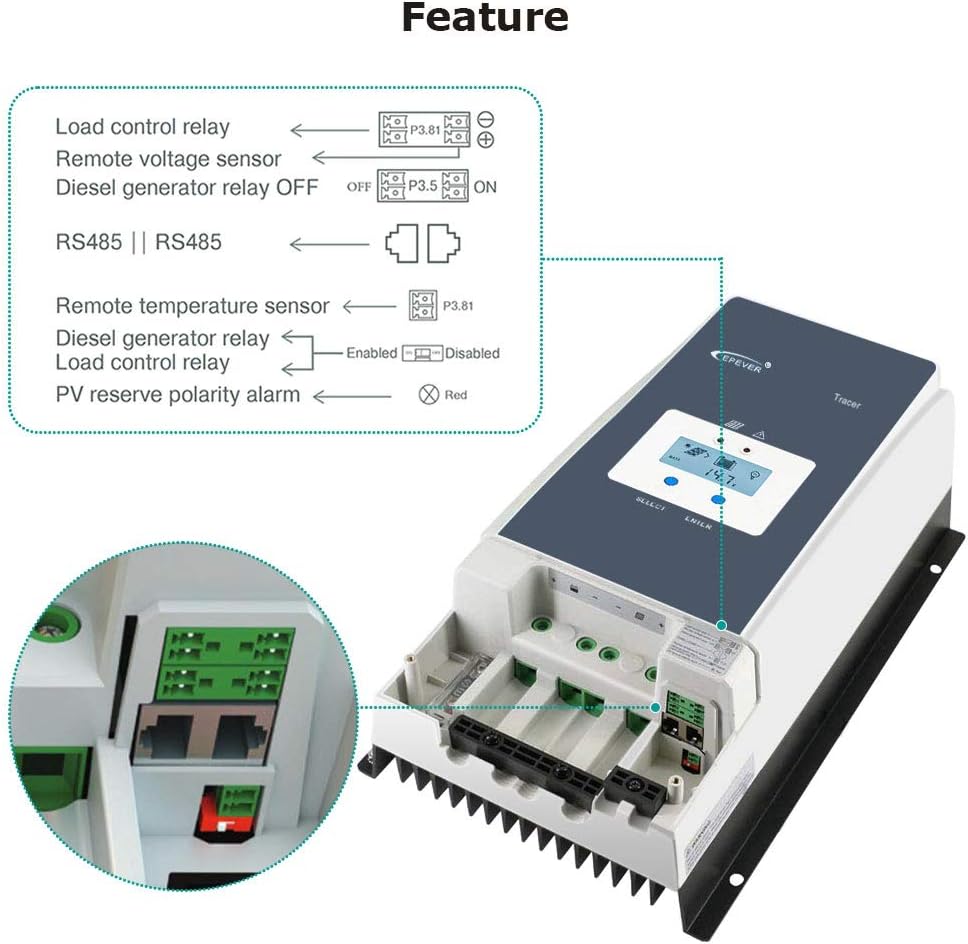
Figure 4.1: Diagram showing various connection features such as load control relay, remote voltage sensor, diesel generator relay, RS485, remote temperature sensor, and PV reverse polarity alarm.
4.3 Passos d'instal·lació
- Muntar el controlador: Securely mount the controller to a vertical surface in a cool, dry, and well-ventilated location using the integrated mounting holes.
- Connecteu la bateria: Connect the battery cables to the battery terminals (2) on the controller. Ensure correct polarity (positive to positive, negative to negative).
- Connect the Solar Panels (PV Array): Connect the solar panel cables to the PV terminals (3) on the controller. Verify correct polarity.
- Connecteu la càrrega (opcional): If using a DC load directly from the controller, connect the load cables to the load terminals (not explicitly numbered in the provided image, but typically adjacent to battery terminals).
- Connect Grounding: Connect the grounding terminal (12) to an earth ground.
- Connexions opcionals: Connect any optional accessories such as the Remote Temperature Sensor (RTS Port 9), RS485 communication cable (Port 8), or relay control cables (Ports 4, 6, 7, 10) as required by your system design.
5. Instruccions de funcionament
Pantalla LCD 5.1 i navegació
The controller features an LCD display for monitoring system status and configuring settings. The display provides information on battery voltage, charging current, PV input, and more. Navigation is typically done using 'SELECT' and 'ENTER' buttons.

Figure 5.1: Close-up of the LCD display showing battery voltage and charging status, alongside the high-efficiency heat dissipation aluminum alloy fins.
5.2 Configuració del tipus de bateria
The Tracer 10415AN supports various battery types: Sealed, Gel, Flooded, and User-defined. It is critical to select the correct battery type in the controller's settings to ensure optimal charging and prolong battery life. Refer to the controller's detailed manual for specific steps on how to adjust these settings via the LCD or external communication tools.
5.3 Control de càrrega
The controller can manage DC loads connected directly to its load terminals. It offers programmable load control modes, allowing users to set timers or activate/deactivate the load based on battery voltage or other parameters. This feature helps prevent over-discharge of the battery.
6. Manteniment
- Inspecció periòdica: Periodically inspect all wiring and connections for loose contacts, corrosion, or damage. Tighten any loose connections.
- Neteja: Keep the controller clean and free from dust and debris. Ensure the heat dissipation fins are not obstructed to maintain optimal cooling.
- Control ambiental: Verify that the installation environment remains within the specified temperature and humidity ranges.
- Salut de la bateria: Monitor de vol de la bateriatage and performance regularly. Ensure the battery type setting matches the installed battery.
- Actualitzacions de firmware: Comproveu el del fabricant weblloc web per a qualsevol actualització de firmware disponible per garantir un rendiment òptim i l'accés a noves funcions.
7. Solució De Problemes
- Sense càrrega:
- Check PV array connections and ensure solar panels are receiving adequate sunlight.
- Verifiqueu les connexions i el volum de la bateriatage.
- Check for blown fuses (1).
- Baix corrent de càrrega:
- Ensure PV array voltage and current are within the controller's specifications.
- Check for shading on solar panels.
- Verify battery type settings are correct.
- La càrrega no funciona:
- Check load connections and ensure the load is not exceeding the controller's rated capacity.
- Comproveu el volum de la bateriatage està per sobre del baix voltagConfiguració de desconnexió electrònica (LVD).
- Check load control settings on the controller.
- Controller Display Off:
- Comproveu les connexions de la bateria i assegureu-vos del volum de la bateriatage està present.
- Ensure the controller is receiving power.
- Codis d'error: Refer to the comprehensive user manual for a list of specific error codes and their corresponding troubleshooting steps.
8. Especificacions tècniques
The EPEVER Tracer 10415AN offers robust performance for various solar applications. Key parameters are detailed below.
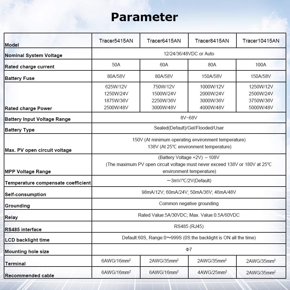
Figure 8.1: Table showing key technical parameters for Tracer AN series controllers, including the Tracer 10415AN.
| Paràmetre | Valor |
|---|---|
| Sistema nominal Voltage | 12V/24V/36V/48V Automàtic |
| Corrent de càrrega nominal | 100A |
| Fusible de la bateria | 150A/58V |
| Potència de càrrega nominal | 1250W/12V, 2500W/24V, 3750W/36V, 5000W/48V |
| Volum d'entrada de bateriatage Rang | 8V-68V |
| Tipus de bateria compatibles | Sealed (Default), Gel, Flooded, User |
| Màx. Circuit obert PV Voltage | 150V (at minimum operating environment temperature), 138V (at 25°C environment temperature) |
| MPP Voltage Rang | (Bateria Voltage +2V) ~ 108V |
| Coeficient de compensació de temperatura | -3mV/°C/2V (per defecte) |
| Autoconsum | 98mA/12V, 60mA/24V, 50mA/36V, 46mA/48V |
| Posada a terra | Common Negative Grounding |
| Relleu | Rated Value 5A/30VDC; Max. Value 0.5A/60VDC |
| Interfície RS485 | RS485 (RJ45) |
| Temps de retroil·luminació LCD | Default: 60S, Range 0~999S |
| Mida del forat de muntatge | Φ7 |
| Terminal | 2AWG/35mm² |
| Cable recomanat | 2AWG/35mm² |
| UPC | 797550115970 |
| Fabricant | SolaMr |
| Dimensions del paquet | 49 x 31.5 x 22.5 cm; 8.46 kg |
| Piles necessàries | No |
| ASIN | B081Z31QVL |
| Número de model de l'article | 100A (Tracer 10415AN) |
| Disponible des de | 26 de novembre de 2019 |
| Tipus de visualització | LCD |
| Temperatura de funcionament | 25 graus centígrads |
9. Garantia i Suport
EPEVER products typically come with a manufacturer's warranty. Please refer to the warranty card included with your product or visit the official EPEVER website for detailed warranty terms and conditions. For technical support, troubleshooting assistance, or warranty claims, please contact the seller or authorized EPEVER service center. The seller for this product is SolaMr-EU.
Per a més ajuda, podeu visitar el EPEVER Store on Amazon.