1. Introducció
This manual provides essential information for the safe and effective installation, operation, and maintenance of the Danfoss MCI 15 Motor Controller, model 037N0039. Please read this manual thoroughly before attempting to install or operate the device. Retain this manual for future reference.
2. Informació de seguretat
Observeu sempre les següents precaucions de seguretat per evitar lesions personals o danys a l'equip:
- La instal·lació i el manteniment només els ha de dur a terme personal qualificat.
- Assegureu-vos que el subministrament elèctric estigui desconnectat abans de realitzar qualsevol cablejat o manteniment.
- Verify all connections are secure and correctly wired according to the provided diagrams.
- Protegiu el dispositiu de la humitat, la pols i les temperatures extremes.
- No feu funcionar el controlador si sembla que està danyat.
3. Producte acabatview
The Danfoss MCI 15 Motor Controller is designed for controlling motor speed and soft starting applications. It features robust construction with an integrated heat sink for efficient thermal management.


4. Especificacions
Key technical specifications for the Danfoss MCI 15 Motor Controller:
| Paràmetre | Valor |
|---|---|
| Número de model | MCI 15 (037N0039) |
| Corrent nominal (Ie) | Max 15 A AC 53a |
| Control Voltage (Uc) | 24-480 V AC/DC |
| Vol. Operatiutage (Ue) | 380-480V 50/60Hz |
| Aïllament Voltage (Ui) | 660 V |
| Impuls Withstand Voltage (Uimp) | 4 kV |
| Dimensions del producte | 5 x 5 x 2 polzades |
| Pes de l'article | 1.35 lliures |
| Material | Copper (heat sink) |
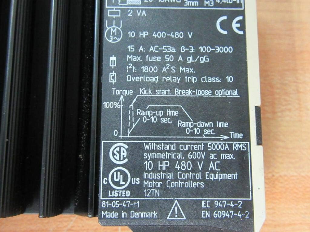
| Fusible màxim | 50 A gL/gG |
| Overload Relay Trip Class | 10 |
| HP Rating (400-480V) | 10 CV |

5. Configuració i instal·lació
5.1 Muntatge
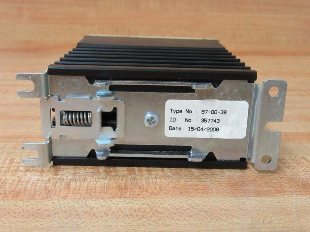
The Danfoss MCI 15 Motor Controller is designed for panel mounting. Ensure adequate ventilation around the heat sink to prevent overheating. Use appropriate fasteners through the mounting brackets shown in Figure 3.4.
5.2 Cablejat
Refer to the wiring diagram on the device label (Figure 4.1) for correct connections. Ensure all wiring adheres to local electrical codes and safety standards.
- Entrada d'alimentació (L1, L2, L3): Connect the three-phase power supply to terminals 1/L1, 3/L2, and 5/L3.
- Motor Output (T1, T2, T3): Connect the motor leads to terminals 2/T1, 4/T2, and 6/T3.
- Control Input (A1, A2): Connecteu el control voltage to terminals A1 and A2.
- Use recommended wire sizes (e.g., 0.75-6mm² or 18-10AWG for power, 0.5-1.5mm² or 20-16AWG for control) and tighten terminals to the specified torque (e.g., 0.5Nm or 4.4lb-in for M3 screws).
5.3 Configuració inicial
Before initial operation, adjust the potentiometers on the front panel (Figure 3.2) to desired settings:
- Ramp Temps de funcionament: Adjust the 'up' potentiometer to set the motor acceleration time (0-10 seconds).
- Ramp Down Time: Adjust the 'down' potentiometer to set the motor deceleration time (0-10 seconds).
- Inici de sessió: Adjust this potentiometer to provide an initial torque boost for starting loads.
- Initial Torque: Adjust this potentiometer to set the initial torque level during startup.
6. Instruccions de funcionament
Once installed and configured, the Danfoss MCI 15 Motor Controller operates by applying a controlled voltagehamp to the motor, providing a soft start and stop. The motor will accelerate to full speed over the set ramp-up time and decelerate over the set ramp-temps d'inactivitat.
- Aplicar control voltage to terminals A1 and A2 to initiate motor operation.
- Remove control voltage to initiate motor stop (soft stop).
- Monitor motor performance and adjust ramp times and torque settings as needed for optimal operation.
7. Manteniment
Regular maintenance ensures the longevity and reliable operation of the motor controller.
- Neteja: Periodically clean the exterior of the controller, especially the heat sink fins, to ensure proper heat dissipation. Use a dry, soft cloth. Do not use solvents or abrasive cleaners.
- Inspecció: Regularly inspect wiring connections for tightness and signs of wear or damage. Check for any discoloration or unusual odors, which may indicate overheating.
- Medi ambient: Assegureu-vos que l'entorn de funcionament es mantingui dins dels rangs de temperatura i humitat especificats.
8. Solució De Problemes
If the motor controller does not operate as expected, consider the following basic troubleshooting steps:
- No Motor Start: Verify power supply to the controller and motor. Check control signal to A1/A2. Ensure all wiring is correct and secure.
- Sobreescalfament del motor: Check for proper ventilation around the heat sink. Ensure the motor is not overloaded. Verify motor parameters are correctly set.
- Incorrect Ramp Horaris: Re-adjust the 'up' and 'down' potentiometers on the front panel.
- Parades inesperades: Check for power fluctuations or intermittent control signals. Inspect for any fault indicators if available on the device or system.
For complex issues, contact Danfoss technical support.
9. Garantia i Suport
Per obtenir informació sobre la garantia del producte, l'assistència tècnica o el servei tècnic, consulteu la pàgina oficial de Danfoss. website or contact your local Danfoss representative. Ensure you have the model number (MCI 15) and serial number (if applicable, visible on the rear label, Figure 7.1) available when contacting support.