1. Introducció
This manual provides detailed instructions for the assembly, operation, maintenance, and troubleshooting of your POWERTEC 71392 Trim Router Table and Router Base Plate. Please read this manual thoroughly before use to ensure safe and efficient operation.
The POWERTEC Trim Router Table is designed for precision routing tasks, offering a stable platform for various woodworking applications. Its compact design is suitable for small to medium-sized workpieces and is compatible with a range of popular trim routers.
2. Components inclosos
- 1x Trim Router Table
- 1x Transparent Bit Guard
- 1x 1/4" Thick Acrylic Base Plate
- 1x Removable Fence
- 2x T-Knobs
- 1x Dust Port
3. Instruccions de configuració
3.1 Desembalatge i inspecció
Carefully remove all components from the packaging. Inspect all parts for any damage. If any parts are missing or damaged, contact POWERTEC customer support before proceeding.
3.2 Attaching the Router to the Base Plate
- Identify the correct pre-drilled holes on the acrylic base plate (POWERTEC 71381) that match your trim router's base. The base plate is designed to fit most trim routers, including models from DeWalt, Makita, Bosch, Ryobi, and Porter Cable. Refer to the compatibility diagram below.
- Align your trim router with the corresponding holes on the acrylic base plate.
- Secure the router to the base plate using the appropriate screws provided with your router or the router table kit. Ensure the router is firmly attached.

Image: The clear acrylic base plate with multiple pre-drilled holes for various trim router models. A router bit is visible through the center opening.

Image: A diagram illustrating the pre-drilled hole patterns on the base plate and their compatibility with various trim router brands and models (DeWalt, Makita, Bosch, Ryobi, Porter-Cable).
3.3 Mounting the Router Table
The router table is designed to be mounted on a workbench or other stable surface. The back edge of the table is pre-drilled to allow for the addition of a clamping strip (not included) for secure attachment. Alternatively, the table can be clamped directly to a workbench using appropriate clamps.

Image: The POWERTEC Trim Router Table securely clamped to a wooden workbench, demonstrating a typical setup for use.
3.4 Attaching the Fence and Bit Guard
- Slide the removable fence onto the table's T-slots.
- Insert the T-knobs into the slots and tighten them to secure the fence at the desired position.
- Attach the transparent bit guard to the fence. The bit guard is height-adjustable via screws for optimal visibility and safety.
- Connect a dust collection system to the 2.5" ID dust port on the fence for efficient chip removal.
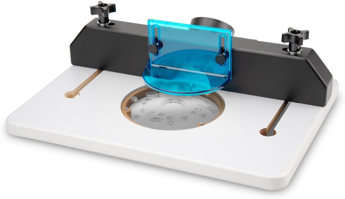
Image: The fully assembled POWERTEC Trim Router Table, showing the white table surface, black fence, clear bit guard, and dust port.

Imatge: Un primer pla view of the transparent, height-adjustable bit guard attached to the router table fence, providing clear visibility of the router bit.

Image: A close-up of the 2.5-inch inner diameter dust collection port integrated into the router table fence, designed for efficient chip extraction.
4. Instruccions de funcionament
4.1 Funcionament general
The POWERTEC Trim Router Table converts your handheld trim router into a stationary tool, allowing for more controlled and precise routing operations. It is suitable for cutting, leveling, jointing, planing, shaping, and general routing of small to mid-sized stock.
4.2 Adjusting Router Bit Height
To adjust the router bit height, it is recommended to detach the router from the table. Set the desired bit height as you would for handheld operation, then re-attach the router to the table. The leveled insert plate ensures the router bit aligns flush with the table surface.
4.3 Using the Adjustable Fence
The adjustable fence allows for precise positioning relative to the router bit. Use the T-knobs to loosen, adjust, and secure the fence. Ensure the fence is parallel to the desired cut line for consistent results. The fence is removable if not required for specific operations.

Image: A workpiece being routed on the table, demonstrating the use of the fence and bit guard for precise cuts.
4.4 Precaucions de seguretat
- Always wear appropriate personal protective equipment (PPE), including eye protection and hearing protection.
- Ensure the router table is securely mounted to a stable surface before operation.
- Keep hands clear of the router bit during operation. Use push sticks or featherboards when necessary.
- Ensure the bit guard is properly positioned for maximum safety and visibility.
- Disconnect power to the router before making any adjustments or changing bits.
5. Manteniment
5.1 Neteja
Regularly clean the router table surface and components to prevent sawdust buildup, which can affect precision and smooth operation. Use a brush or vacuum to remove dust and debris. For stubborn residue, a damp cloth can be used, ensuring the surface is dried thoroughly afterward.
5.2 Emmagatzematge
Store the router table in a dry environment to prevent moisture damage, especially to the MDF components. Keep all parts together to avoid loss.
6. Solució De Problemes
6.1 Router Not Fitting Base Plate
Ensure you are using the correct pre-drilled holes for your specific router model. Refer to the compatibility diagram in Section 3.2. If your router has a plunge base, verify that its diameter and screw head protrusions are compatible with the base plate's design. Some plunge bases may have a larger diameter than the base plate's recess, preventing a flush fit.
6.2 Base Plate Not Level with Table Surface
Check the leveling screws on the base plate. Adjust them as needed to ensure the base plate sits flush with the router table surface. Unevenness can affect routing accuracy.
6.3 Fence Adjustment Issues
If the fence does not adjust smoothly or secure properly, check the T-slots for any obstructions or debris. Ensure the T-knobs are fully engaged and threaded correctly. If a knob is difficult to turn, do not force it; inspect the threading for damage.
6.4 Ineffective Dust Collection
Ensure the dust port is securely connected to your dust collection system. Check for any blockages in the dust port or hose. Verify that your dust collector has sufficient suction for the type of material being routed.
7. Especificacions
- Número de model: 71392
- Material: MDF (Table), Acrylic (Base Plate)
- Pes de l'article: 5.9 lliures
- Dimensions del producte: 16.3 x 11.1 x 4.3 polzades
- Dust Port ID: 2.5 polzades
- Compatibilitat: Fits most trim routers from DeWalt, Makita, Bosch, Ryobi, Porter Cable
8. Garantia i Suport
For warranty information or technical support, please contact POWERTEC customer service. Refer to the product packaging or the official POWERTEC website for contact details. Keep your purchase receipt for warranty claims.


