1. Introducció
This manual provides comprehensive instructions for the installation, operation, maintenance, and troubleshooting of the FLIPSKY FSESC75200 Electronic Speed Controller (ESC). The FSESC75200 is a high-performance, high-current ESC designed for demanding applications such as E-foils, fighting robots, electric surfboards, and AGV robots. It features robust power handling, advanced control options, and multiple communication interfaces.
2. Informació de seguretat
Please read and understand all safety warnings and precautions before operating the FSESC75200. Failure to do so may result in serious injury, damage to the ESC, or damage to other components.
- Vol. Alttage i actual: This ESC operates at high voltages (up to 75V) and handles high currents (up to 200A continuous, 300A peak). Always exercise extreme caution when working with electrical systems. Disconnect power before making any connections or disconnections.
- Cablejat adequat: Ensure all connections are secure and correctly polarized. Incorrect wiring can cause immediate damage to the ESC and connected components. Use appropriate wire gauges (8AWG for motor, 10AWG for power) as specified.
- Aïllament: Insulate all exposed wires and connections to prevent short circuits.
- Gestió de la calor: The ESC can generate significant heat during operation. Ensure adequate cooling, especially during high-load applications. The aluminum heatsink helps dissipate heat, but additional cooling may be required depending on the application.
- Exposició a l'aigua: While the ESC has an IP67 waterproof level with a water cooling enclosure, direct exposure to water without proper sealing can cause damage. Ensure all seals are intact if operating in wet environments.
- Firmware i programari: Only use official FLIPSKY firmware and VESC Tool software for configuration. Incorrect firmware or settings can lead to unpredictable behavior or damage.
- Compatibilitat de la bateria: Ensure your battery pack voltage (3-16S) is within the safe operating range of the ESC (14-75V).
3. Producte acabatview
The FLIPSKY FSESC75200 is a robust Electric Speed Controller designed for high-power applications. It features a durable aluminum heatsink for efficient thermal management and supports various control modes.
3.1 Característiques clau
- Voltage Range: 14-75V (safe for 3-16S LiPo batteries)
- Corrent continu: 200A
- Corrent màxima: 300A
- Supported Sensors: ABI, HALL, AS5047, AS5048A
- EPRM: 150000
- Regenerative Braking capability
- Sensored, Sensorless, and Hybrid operation modes
- Configurable RPM, current, voltage, and power limits
- Input Sources: PPM, Analog, NRF Nyko Kama Nunchuck
- Communication Ports: USB, CAN, UART
- corba de l'accelerador i ramping per a totes les fonts d'entrada
- Operació perfecta de 4 quadrants
- revolució motora, amp recompte d'hora, watt hora
- Real-time data analysis and readout via communication ports
- Adjustable protection against: Low/High input voltage, High motor/input current, High regenerative braking current, High RPM.
- Digital VCC and analog VCC produced by separate voltage regulators for accurate AD conversion.
- Waterproof level (with water cooling enclosure): IP67
3.2 Identificació de components
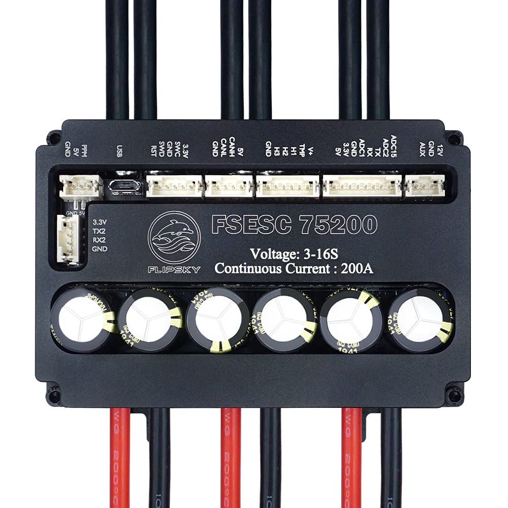
Figura 3.2.1: superior view of the FSESC75200 showing the main board, capacitors, and various connection ports. The large black cables are for motor connections, and the red/black cables are for battery input.

Figure 3.2.2: Package contents of the FSESC75200, including the ESC unit, USB cable for configuration, and various JST-PH cables for sensor and communication connections.
3.3 Port and Pinout Diagram

Figure 3.3.1: Detailed pinout diagram of the FSESC75200. This diagram illustrates the location and function of each port, including UART, PPM, USB, SWD, CAN, SENSE, COMM, and AUX ports, along with their respective pin assignments for proper connection of external devices and sensors.
Refer to Figure 3.3.1 for a detailed layout of all communication and sensor ports. Key ports include:
- UART (1): Universal Asynchronous Receiver/Transmitter for serial communication (e.g., Bluetooth modules, external microcontrollers).
- PPM (2): Pulse Position Modulation input for standard RC receivers.
- USB (3): Micro-USB port for connecting to a computer for configuration via VESC Tool.
- SWD (4): Serial Wire Debug port for advanced debugging and firmware flashing.
- CAN (5): Controller Area Network bus for multi-ESC setups or communication with other CAN-enabled devices.
- SENSE (6): Sensor port for Hall sensors (H1, H2, H3), temperature sensor (TMP), and voltage reference (V+).
- COMM (7): Communication port with ADC inputs (ADC1, ADC2), TX/RX, and 3.3V/5V power outputs.
- AUX (8): Auxiliary port with 12V and GND outputs.
4. Configuració
Proper setup is crucial for the safe and efficient operation of the FSESC75200. Follow these steps carefully.
4.1 Connexions de maquinari
- Connexió de la bateria: Connect your battery pack to the main power cables (red for positive, black for negative) of the ESC. Ensure correct polarity. Use high-quality connectors (e.g., XT90, AS150) capable of handling high currents. The power cable is 10AWG.
- Connexió del motor: Connect the three motor phase wires to the corresponding large black cables of the ESC. The motor wire is 8AWG. For sensorless operation, the order does not matter initially, but for sensored operation, ensure Hall sensor wires are connected correctly to the SENSE port.
- Connexió del dispositiu d'entrada:
- PPM (RC Receiver): Connect the signal wire from your RC receiver to the PPM port. Ensure 5V and GND are also connected.
- UART (e.g., Bluetooth Module): Connect your UART device to the UART port, matching TX/RX and power pins.
- Bus CAN: For multi-ESC setups, connect the CAN H and CAN L lines between ESCs.
- Connexió del sensor (opcional): If using a sensored motor, connect the Hall sensor wires and temperature sensor wire from the motor to the SENSE port on the ESC. Refer to the motor's documentation for pinout.
4.2 Software Configuration (VESC Tool)
The FSESC75200 is configured using the VESC Tool software. This software allows you to calibrate your motor, set limits, and customize various parameters.
- Download VESC Tool: Obtain the latest version of VESC Tool from the official VESC project website or FLIPSKY's support page.
- Connect ESC to PC: Connect the FSESC75200 to your computer using the provided Micro-USB cable.
- Launch VESC Tool: Open the VESC Tool software.
- Connect to ESC: In VESC Tool, select the correct COM port and click "Connect".
- Actualització del firmware (recomanada): Check for and install the latest stable firmware for the FSESC75200. Follow the on-screen prompts carefully.
- Motor Setup Wizard: Run the Motor Setup Wizard. This wizard will guide you through:
- Motor Detection: Automatically detects motor parameters (resistance, inductance, flux linkage).
- Hall Sensor Detection (if applicable): Calibrates Hall sensors for sensored operation.
- Configuració d'entrada: Configures your input device (PPM, UART, etc.) and calibrates throttle ranges.
- Establir límits: Configure current limits (motor and battery), voltage limits (min/max input), RPM limits, and temperature limits according to your motor, battery, and application requirements.
- Desa la configuració: After making all necessary adjustments, save the configuration to the ESC.
5. Funcionament
Once the FSESC75200 is properly set up, you can begin operation. Always perform initial tests in a controlled environment.
5.1 Funcionament bàsic
- Encès: Connect the battery to the ESC. The ESC will typically emit a series of beeps indicating successful power-up and motor detection (if sensored).
- Control d'entrada: Use your configured input device (e.g., RC remote, joystick) to control the motor.
- Seguiment: Utilize the real-time data analysis features of VESC Tool (via USB or UART/Bluetooth module) to monitor motor RPM, current, voltage, temperature, and other parameters during operation. This helps in identifying potential issues and optimizing performance.
5.2 Advanced Settings and Modes
- Sensored vs. Sensorless vs. Hybrid:
- Sensored: Provides smooth startup and low-speed control, ideal for applications requiring precise control from standstill. Requires Hall sensors on the motor.
- Sensorless: Operates without Hall sensors, relying on back-EMF for commutation. Simpler wiring but may have less smooth startup.
- Híbrid: Combines both, using sensors for low speed and switching to sensorless at higher RPMs for efficiency.
- Throttle Curve and Ramping: Adjust these settings in VESC Tool to customize the responsiveness and feel of your throttle input. Ramping allows for smoother acceleration and deceleration.
- Frenada regenerativa: The ESC supports regenerative braking, which recharges the battery during deceleration. Configure the braking current limits carefully to avoid overcharging the battery.
- Característiques de protecció: The FSESC75200 includes various adjustable protection mechanisms. These are critical for preventing damage:
- Vol d'entrada baix/alttage Protecció
- High Motor/Input Current Protection
- High Regenerative Braking Current Protection
- High RPM Protection
- Over-temperature Protection (MOSFETs and Motor)
6. Manteniment
Regular maintenance ensures the longevity and reliable performance of your FSESC75200.
- Neteja: Keep the ESC clean and free from dust, dirt, and debris. Use a soft, dry brush or compressed air. If operating in wet conditions, ensure the enclosure is properly sealed and clean any external residue after use.
- Inspecció: Periodically inspect all wiring and connections for signs of wear, fraying, or corrosion. Ensure all connectors are securely seated. Check the heatsink for any obstructions that might impede airflow.
- Actualitzacions de firmware: Regularly check for and install official firmware updates from FLIPSKY or the VESC project. Updates often include performance improvements, bug fixes, and new features.
- Emmagatzematge: When not in use for extended periods, store the ESC in a cool, dry place, away from direct sunlight and extreme temperatures. Disconnect it from the battery.
7. Solució De Problemes
This section provides solutions to common issues you might encounter with the FSESC75200.
| Problema | Causa possible | Solució |
|---|---|---|
| L'ESC no s'encén. | No power from battery; incorrect battery connection; faulty power switch/connector. | Comproveu el volum de la bateriatage. Verify battery connections for correct polarity and secure fit. Test power switch if applicable. |
| Motor not spinning or erratic behavior. | Incorrect motor wiring; Hall sensor issue; motor detection failed; incorrect VESC Tool settings. | Verify motor phase wire connections. Re-run Motor Setup Wizard in VESC Tool, ensuring Hall sensor detection is successful if using sensored mode. Check input device calibration. |
| ESC overheating. | Insufficient cooling; excessive load; incorrect motor/battery current limits. | Ensure adequate airflow around the heatsink. Reduce load or operating time. Review and adjust motor/battery current limits in VESC Tool. Consider additional cooling solutions. |
| Unexpected shutdowns or power cuts. | Voltage cutoffs (low/high); overcurrent protection; over-temperature protection. | Comproveu el volum de la bateriatage under load. Review VESC Tool logs for fault codes. Adjust voltage cutoff limits if too aggressive. Ensure current and temperature limits are appropriate for your setup. |
| Cannot connect to VESC Tool via USB. | Driver issue; incorrect COM port selected; faulty USB cable/port. | Install necessary USB drivers. Verify COM port in Device Manager. Try a different USB cable or port. Ensure ESC is powered on. |
For more detailed troubleshooting and fault code explanations, refer to the VESC project documentation or FLIPSKY's online support resources.
8. Especificacions
Detailed technical specifications for the FLIPSKY FSESC75200.
| Paràmetre | Valor |
|---|---|
| Voltage Rang | 14-75V (3-16S LiPo safe) |
| Corrent continu | 200A |
| Corrent màxim | 300A |
| EPRM | 150000 |
| Sensors compatibles | ABI, HALL, AS5047, AS5048A |
| Ports de comunicació | USB, CAN, UART |
| Calibre del cable del motor | 8 AWG |
| Calibre del cable d'alimentació | 10 AWG |
| Nivell impermeable | IP67 (with water cooling enclosure) |
| Material del dissipador de calor | Alumini |
| Tipus de muntatge | Muntatge del xassís |
| Pes de l'article | 14.08 unces (aprox. 400 g) |
8.1 Dimensions

Figure 8.1.1: Dimensions of the FSESC75200. The unit measures approximately 110mm in length, 73mm in width, and 34mm in height (including components), with a base height of 26mm.
- Length: Approximately 110mm
- Width: Approximately 73mm
- Height: Approximately 34mm (total), 26mm (base)
9. Garantia i Suport
FLIPSKY products are designed for high performance and reliability. For warranty information and technical support, please refer to the official FLIPSKY weblloc web o contacteu directament amb el seu servei d'atenció al client.
- Garantia: Els termes i condicions específics de la garantia poden variar. Si us plau, conserveu el comprovant de compra per a reclamacions de garantia.
- Suport tècnic: For technical assistance, troubleshooting beyond this manual, or inquiries about parts and accessories, visit the FLIPSKY official website for FAQs, forums, and contact information.


