1. Introducció
Thank you for choosing the Cloudray 30W SPT Radio Frequency (RF) CO2 Laser Tube. This laser source operates at a wavelength of 10600nm and is specifically designed for integration into CO2 laser engraving and marking machines. This manual provides essential information for the safe and effective installation, operation, and maintenance of your laser tube.
The operation control of the N30 CO2 RF laser is straightforward, and the laser can be controlled or tested according to the RG45 interface definition.
2. Informació de seguretat
WARNING: INVISIBLE LASER RADIATION
This product emits invisible laser radiation. Avoid eye or skin exposure to direct or scattered radiation. This is a Class 4 laser product, capable of causing severe eye and skin damage. Always wear appropriate laser safety eyewear and follow all safety protocols when operating or servicing this device.
Ensure the laser is installed in a controlled environment with proper ventilation and interlocks. Never look directly into the laser beam or its reflections. Disconnect power before performing any maintenance or installation procedures.

Figura 2.1: superior view of the laser tube showing the invisible laser radiation warning label.
3. Producte acabatview
The Cloudray SPTN30A RF CO2 Laser Tube is a compact and robust laser source. Key components include the laser cavity, reflective lens, laser output window, RF power supply, and RJ45 power/control interface.

Figure 3.1: Cloudray 30W SPT RF CO2 Laser Tube.

Figure 3.2: Labeled components of the N30A Laser.
4. Especificacions
The following table details the technical specifications of the Cloudray SPTN30A RF CO2 Laser Tube:
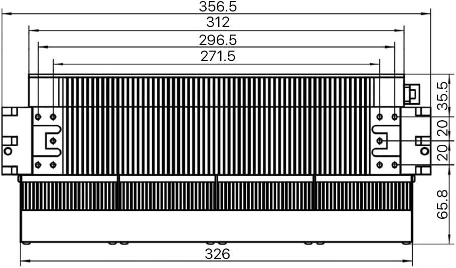
Figure 4.1: Technical Specifications Table.
4.1. Dimensions físiques
The dimensions of the laser tube are critical for proper integration into your system. Refer to the diagrams below for detailed measurements.

Figura 4.2: Frontal view dimensions.

Figure 4.3: Comprehensive dimensional drawings (all views).
5. Configuració i instal·lació
5.1. Requisits d'alimentació
The laser tube requires a +48VDC power supply with a maximum current of 12 Amps. Input voltage should not exceed +50VDC. Ensure your power supply meets these specifications to prevent damage to the laser.

Figure 5.1: Power input and RJ45 interface.
5.2. Esquema de cablejat
Connect the laser tube to the 48V DC power supply, control card, and external monitoring equipment as shown in the diagram below. Ensure all connections are secure and correct polarity is observed.

Figure 5.2: System wiring diagram.
5.3. RJ45 Interface Pin Definition
The RJ45 interface is used for control signals. Refer to the pinout diagram and signal description table for proper connection and control.

Figure 5.3: RJ45 Pinout Diagram.

Figure 5.4: RJ45 Signal Description Table.
- Pin 1 (TTL Signal Input): Set to high level (1) for RF ON, low level (0) for RF OFF. Input impedance 1KΩ.
- Pin 2 (Output Voltage): +15±0.5VDC, Output Current 250mA. Used to detect RF power supply. If voltage is out of range, return for maintenance.
- Pin 3 (LASER OK): Input TTL level. 1=No Failure On Laser, 0=Laser Failure. In pre-ionization process after adding DC48V, pin is at low level. Add TTL signal after detecting output high level of this pin.
- Pin 4 (Temperature OK): Output TTL level. 1=Temperature is normal, 0=Temperature is wrong. If laser temperature exceeds 65°C, an error is reported and a low level is output. Laser temperature protection stops automatically.
- Pin 5 (Voltage OK): Output TTL level. 1=Voltage is normal, 0=Voltage is wrong. If DC power supply voltage exceeds 55V, an error is reported and a low level is output.
- Pin 6 (Grounding): Special for internal test.
- Pin 7 (Control Enable): After pin is set to high level, the laser is enabled. At this time, the laser can be emitted when the high level is added to pin 1.
- Pin 8 (Signal Grounding): All signal grounds must be connected to pin 8.
6. Instruccions de funcionament
Once properly installed and connected, the laser tube's operation is controlled via the RJ45 interface signals. Ensure all safety precautions are in place before powering on the laser.
- Encès: Apply the specified +48VDC power to the laser tube.
- Enable Laser: Set Pin 7 (Control Enable) to a high TTL level to enable the laser.
- Laser Emission: Once enabled, set Pin 1 (TTL Signal Input) to a high TTL level to initiate laser emission. Set to low to stop emission.
- Seguiment: Monitor the status of the laser using the feedback signals from Pin 3 (LASER OK), Pin 4 (Temperature OK), and Pin 5 (Voltage OK).
- Modulació: The laser supports modulation via the control signals, allowing for precise power control within the 0-100% duty ratio range and 0-25KHz modulation frequency.
7. Manteniment
Regular maintenance ensures optimal performance and longevity of your laser tube. Always disconnect power before performing any maintenance.
- Sistema de refrigeració: The laser tube features integrated cooling fans. Ensure these fans are free from dust and obstructions to maintain proper airflow and prevent overheating. Periodically clean the fan blades and heat sinks.
- Components òptics: Keep the laser output window and reflective lens clean. Use only approved optical cleaning methods and materials to avoid damaging the delicate surfaces.
- Connexions: Periodically check all electrical connections, especially the power and RJ45 cables, to ensure they are secure and free from corrosion or damage.

Figure 7.1: Cooling fans on the laser tube.
8. Solució De Problemes
This section provides guidance for common issues. Refer to the RJ45 Signal Description Table (Figure 5.4) for diagnostic signals.
- Sense emissió de làser:
- Check power supply: Ensure +48VDC is stable and within limits. Verify Pin 5 (Voltage OK) is high.
- Check control signals: Ensure Pin 7 (Control Enable) is high and Pin 1 (TTL Signal Input) is high.
- Check LASER OK signal: If Pin 3 (LASER OK) is low, it indicates a laser failure.
- Overheating Indication:
- If Pin 4 (Temperature OK) is low, the laser temperature has exceeded 65°C.
- Check cooling fans for obstructions or malfunction.
- Ensure adequate ventilation around the laser tube.
- Unstable Output Power:
- Verificar l'estabilitat del subministrament elèctric.
- Check for clean optical components.
- Ensure proper grounding (Pin 8).
9. Garantia i Suport
The Cloudray SPTN30A RF CO2 Laser Tube comes with a manufacturer's warranty. Please refer to your purchase documentation for specific warranty terms and conditions. Note that tampering with the product, such as breaking the warranty seal, may void the warranty.
Figure 9.1: Warranty seal location.
For technical support, troubleshooting assistance, or warranty claims, please contact Cloudray customer service through the official channels provided at the time of purchase or visit the Cloudray official weblloc.
Cloudray Official Store: Visit Cloudray Store on Amazon


