1. Introducció
This manual provides detailed instructions for the assembly, operation, maintenance, and troubleshooting of your Luqeeg 6DOF Robot Arm MG996R. This programmable mechanical arm is designed for educational purposes, DIY projects, and demonstrating robotic manipulation principles.
The power system consists of six MG996 analog servo motors, enabling precise control over the arm's movements, including front-to-back, up-and-down, and left-to-right gripping. The robust construction utilizes 2mm thick aluminum plates for enhanced stability, and imported cup bearings at the steering joints ensure flexible and centered steering.
2. Contingut del paquet
Abans de començar el muntatge, comproveu que tots els components que s'enumeren a continuació siguin presents al vostre paquet:
- 6 x MG996 Analog Steering Gear (Servo Motors)
- 1 x Brida de cable
- 4 Packs Screw Nut Fittings (various sizes)
- 3 x Extension Cords
- 1 x Flange Rod
- 3 x Flange Bearings
- 6 x Metal Steering Wheels (Servo Horns)
- 1 x Mechanical Arm (main structure)
- 1 x Biga
- 1 x Different U-Shaped Bracket
- 2 x L-Shaped Brackets
- 2 x Long U Brackets
- 4 x Multi-Function Brackets

Image: All components of the Luqeeg 6DOF Robot Arm laid out, including servo motors, various metal brackets, screws, and cables.
3. Muntatge i muntatge
Assembly of the Luqeeg 6DOF Robot Arm requires careful attention to detail. It is highly recommended to have a PWM driver or servo tester available to center the servos before assembly. This kit does not include a controller for the servos.
3.1 Eines necessàries (no incloses)
- PWM driver or 6-servo tester
- Thin 5.5mm box end wrench
- Narrow jaw needle-nose pliers
- Tornavís petit Phillips
- Sandpaper or file (for gripper modification, if needed)
- M3 washers, nuts, and spacers (optional, for gripper modification)
3.2 Screw Identification
- Washer head screws: Used for mounting servos. Their wider head prevents sliding through plastic. Approximately 24 needed with nuts.
- Smallest screws: Used for mounting aluminum servo horns onto servos, metal parts onto servo horns, and L-brackets to the aluminum cylinder arm. Approximately 27 needed.
- Medium screws: Used for attaching U-brackets back-to-back, stand halves back-to-back, pivot servo to the stand, and L-brackets onto servo mounts. Approximately 10+ needed with bolts.
- Long screws: Used for attaching pivots on the arms together through bearings. Approximately 3 needed.
3.3 Pre-Assembly Steps
- Center Servos: Connect each servo to a PWM driver or servo tester and set them to their center position. This is critical for proper alignment.
- Attach Servo Horns: Attach all aluminum servo horns to the servos, but do not secure them with screws yet.
- Inspect Gripper Standoffs: Check the length of the standoffs on the claw grabber. If they are too long, the servo may not seat properly, and the horn might bind. Sand down the standoffs by approximately 2mm if necessary to ensure the servo fits flush against the claw and its horn.
3.4 Seqüència de muntatge
- Muntatge de la base:
- Connect the two stand halves back-to-back using medium screws.
- Attach the two U-brackets back-to-back using medium screws.
- Mount the bottom servo to the assembled stand using washer head screws. This servo will control the Z-axis pivot.
- Lower Arm Assembly:
- Attach the L-brackets (short sides) onto the aluminum cylinder, facing away, using small screws.
- Attach the aluminum L-bracket arm to two metal servo mount cages using medium screws, ensuring they match the product photos for orientation.
- Place bearings on the outside of the U-bracket arm. Insert a long screw through a servo mount cage, centered with the servo's axis, through the bearing to create a pivot. Secure with a nut on the outside. Consider adding two washers between the bearing and the next arm to prevent rubbing.
- Repeat the previous step for other linkages to form the arm segments.
- Servo Integration (Arm Joints):
- Attach the servo horn to the servo cage at the base and secure it with a small screw.
- Mount the bottom servo at the base of the arm. Use small screws on the metal arm side, ensuring it faces directly upwards. Mount its horn onto the servo with another small screw.
- Attach the next servo to the joint merging the aluminum cylinder arm to the U-bracket arm at a 90-degree angle. The cylinder arm should be level, and the first arm straight up.
- Repeat this process for the subsequent servo, attaching the U-bracket pointing straight down, 90 degrees off from the middle arm (which should be level).
- Gripper Assembly:
- Mount the claw swivel servo and secure its horn with a small screw.
- Use two small screws to mount the claw onto the servo horn.
- Attach the claw's servo to the arm using washer head screws.
- Secure the claw's "hat" (gear) to the claw mechanism with small screws.
- Ajustaments finals:
- Consider adding springs to the first two joints if the arm's weight causes instability.
- Ensure all connections are secure but allow for free movement of joints.

Image: An assembled Luqeeg 6DOF Robot Arm, showcasing its full structure and claw mechanism.
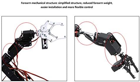
Imatge: Detallada view of the forearm mechanical structure, emphasizing its simplified design for easier installation and flexible control.
4. Instruccions de funcionament
The Luqeeg 6DOF Robot Arm is controlled by six servo motors. To operate the arm, you will need an external servo controller (e.g., Arduino, Raspberry Pi, or a dedicated servo driver board) capable of generating Pulse Width Modulation (PWM) signals.
4.1 Connecting Servos
- Each servo has three wires: power (red), ground (brown/black), and signal (orange/yellow).
- Connect the power and ground wires of all servos to a suitable power supply (4.8V-7.2V). Ensure the power supply can provide sufficient current for all six servos, especially when they are under load.
- Connect each servo's signal wire to a dedicated PWM output pin on your chosen servo controller.
- Use the provided extension cords if necessary to reach your controller.
4.2 Programming and Control
The control of the robot arm involves sending specific PWM signals to each servo to dictate its angular position. The MG996 servos typically operate with a pulse length between 73 and 536 (out of 4096) at 50Hz, corresponding to their 180-degree range.
- Biblioteques de programari: Many microcontrollers have dedicated servo libraries (e.g., Arduino Servo library) that simplify controlling servo positions.
- Inverse Kinematics: For advanced control, such as moving the gripper to a specific (x, y, z) coordinate, you will need to implement inverse kinematics algorithms in your programming.
- Seguretat: Always operate the arm in a clear space. The servos are powerful and can cause injury if fingers or other objects are caught in moving parts.

Image: A user interacting with the robot arm, likely programming or testing its movements, with a laptop in the background.
5. Manteniment
Regular maintenance ensures the longevity and optimal performance of your robot arm.
- Inspecció conjunta: Periodically check all screws and nuts for tightness. Vibrations during operation can loosen fasteners.
- Lubricació de rodaments: The cup bearings at the steering joints are generally self-lubricating, but if you notice stiffness or unusual noise, a small amount of dry lubricant (e.g., PTFE spray) can be applied. Avoid oil-based lubricants that attract dust.
- Servo Health: Listen for unusual noises from the servos. Excessive strain or continuous buzzing may indicate a problem or that the servo is being pushed beyond its limits.
- Gestió de cables: Ensure all wires are neatly routed and secured with cable ties to prevent them from snagging on moving parts or being pinched.
- Neteja: Keep the arm free from dust and debris. Use a soft, dry cloth for cleaning.
6. Solució De Problemes
This section addresses common issues you might encounter with your robot arm.
6.1 Arm Does Not Move or Moves Erratically
- Font d'alimentació: Verify that the power supply is connected correctly and provides adequate voltage (4.8V-7.2V) and current. Insufficient current can lead to weak or erratic movement.
- Servo Connections: Check all servo signal, power, and ground connections to the controller and power supply. Ensure they are secure and correctly oriented.
- Senyals PWM: Confirm that your servo controller is generating correct PWM signals within the expected range for the MG996 servos.
- Servo Damage: A faulty servo may need replacement. Test individual servos if possible.
6.2 Weak or Unstable Arm Movement
- Estanquitat de les articulacions: Ensure all screws are tightened appropriately. Loose joints can cause instability.
- Servo Torque: The MG996 servos have a specified torque. If the arm is lifting heavy objects or extending too far, it might exceed the servo's capabilities. Consider adding springs to assist the initial joints if the arm's weight is an issue.
- Font d'alimentació: As above, ensure the power supply can handle the peak current draw when all servos are active and under load.
6.3 Gripper Binding or Not Engaging Properly
- Standoff Length: Re-check the gripper standoffs. If they are too long, the servo horn may bind against the base plate. Sanding them down or using M3 washers/spacers to adjust the height can resolve this.
- Servo Horn Engagement: Ensure the servo spline fully engages with the servo horn. If it's loose, the gripper will be sloppy. Adjust the horn's position or use shims if necessary.
- Bent Parts: Inspect the gripper rotation bracket and other metal parts for any bends that might impede movement. Gently bend them back into place if found.
6.4 Difficulty with Assembly
- Pre-center Servos: Always center your servos using a PWM driver before attaching any mechanical parts. This ensures correct initial alignment.
- Vegeu els diagrames: Amb cura review product images and diagrams for correct orientation of brackets and components.
- Tipus de cargols: Use the correct screw types for each application (e.g., washer head for servos, smallest for horns).
7. Especificacions
| Característica | Especificació |
|---|---|
| Model | MG996R |
| Degrees of Freedom (DOF) | 6 |
| Tipus de servo | MG996 Analog Steering Gear |
| Voltage | 4.8 V - 7.2 V |
| Corrent sense càrrega | 100 mA |
| Machine Torsion (Torque) | 10 kg.cm |
| Limit Angle | 180° |
| Longitud del cable | 30 cm |
| Material de l'engranatge | Metal Gear |
| Temps Mort | 5 uS |
| Material | Acer d'aliatge, alumini |
| Pes de l'article | 2.05 lliures (aprox. 0.93 kg) |
| Dimensions del paquet | 9.92 x 6.81 x 2.01 polzades (aprox. 25.2 x 17.3 x 5.1 cm) |

Image: Dimensional drawing of the robot arm, indicating its reach and overall size.
8. Garantia i Suport
8.1 Informació de la garantia
Specific warranty details for the Luqeeg 6DOF Robot Arm MG996R are not provided in this manual. Please refer to the product packaging or the retailer's website for the most current warranty information. Keep your purchase receipt as proof of purchase.
8.2 Atenció al client
For technical assistance, missing parts, or any questions regarding your Luqeeg product, please contact Luqeeg customer support through the retailer where the product was purchased or visit the official Luqeeg brand store online.
Luqeeg Brand Store: Visit Luqeeg Store


