1. Introducció
1.1 Producte acabatview
The DALY BMS (Battery Management System) is designed to protect 24-series 72V LiFePO4 battery packs, supporting a continuous discharge current of 100A. This module ensures optimal performance and extends the lifespan of your battery by providing essential protection features.
Les característiques clau inclouen:
- Protecció contra sobreintensitat
- Protecció de sobrecàrrega
- Protecció de sobredescàrrega
- Protecció contra curtcircuits
- Protecció de temperatura
- Integrated balance leads for cell voltage equalization.
The robust design incorporates injection patent technology and a patent shell, offering waterproof, dustproof, shockproof, and anti-static properties. High-quality components ensure pressure resistance and durability.
1.2 Contingut del paquet
Verifiqueu que tots els elements siguin presents al vostre paquet:
- DALY 3.2V LiFePO4 BMS (1 unit)
- NTC Sensor (1 unit)
- Sampling Cable (1 unit)
- Manual d'instruccions (1 unitat)

Figura 1: Example of package contents including the BMS unit, cables, and manual.
2. Informació de seguretat
Read all safety warnings and instructions carefully before installation and operation. Failure to follow these instructions may result in electric shock, fire, or serious injury.
- Sempre utilitzeu equips de protecció individual (EPI) adequats, incloent-hi ulleres de seguretat i guants aïllants, quan treballeu amb bateries.
- Ensure the battery pack is disconnected from any power source before installing or servicing the BMS.
- Verify correct polarity for all connections. Incorrect wiring can damage the BMS, battery, or connected equipment, and poses a fire risk.
- Do not short-circuit the battery terminals or BMS connections.
- Keep the BMS and battery pack away from water, moisture, and flammable materials.
- Do not attempt to open, modify, or repair the BMS. Refer servicing to qualified personnel.
- Ensure adequate ventilation around the battery pack and BMS during operation.
- El sampling cable must be connected correctly and in sequence. Connecting the sampling cable incorrectly can damage the BMS.
3. Configuració i instal·lació
3.1 Esquema de cablejat
The following diagram illustrates the common port wiring for the DALY BMS. Ensure all connections are made accurately according to this diagram.

Figura 2: Common port wiring diagram for the DALY BMS. This diagram shows connections for the motor load, charger, and battery cells, along with sampling wires.
3.2 Connection Sequence
Follow these steps carefully to connect the protection board and battery:
- Important: The cables of different manufacturers are not universal. Please ensure to use the supporting cables provided with your DALY BMS. When welding the sampling cable, the cable shall no be inserted into the BMS until all welding is complete.
- El sampling line is connected from the thin black line to the total negative electrode B-. The second line (red line) is connected to the positive electrode of the first string of batteries, followed by the positive electrode of each string of batteries until the last string of total positive electrode B+.
- After the cable is connected, the plug should not be directly inserted into the BMS. First, measure the voltage between each two adjacent metal terminals on the back of the plug. In the case of Li-ion battery, the voltage should be between 3.0 ~ 4.15V. For LiFePO4 battery, the voltage should be between 2.5 ~ 3.6V. For LTO battery, it should be between 1.8 ~ 2.8V. Please ensure that the voltage is correct before proceeding to the next step.
- Connect the B- wire (blue thick wire) of the protection plate to the negative pole of the battery.
- Insert the cable into the BMS.
After wiring:
- Please measure whether the battery B+, B-voltage and B+, P-voltage are equal (i.e., whether the voltage of the battery pack itself is equal to the voltage after passing through the protection board). Equal means that the BMS can be used normally. If not, please recheck according to the above wiring sequence.
- The positive electrodes of the charge and discharge terminals are directly connected to the total positive electrode B+ of the battery.
- The wiring method of the common port BMS is that the negative electrodes of charge and discharge are connected at the P- of the protection board.
For additional visual guidance, you may refer to the official website's picture tutorial: DALY Electronics Wiring Tutorial
4. Instruccions de funcionament
Once the DALY BMS is correctly installed and connected to your LiFePO4 battery pack, it operates automatically to provide continuous protection. This standard BMS model does not feature communication functions (e.g., Bluetooth, RS485, CAN).
- Protecció automàtica: The BMS continuously monitors cell voltage, current, and temperature. It will automatically cut off charge or discharge if any parameter exceeds safe limits (overcharge, overdischarge, overcurrent, short circuit, or over-temperature).
- Balance Function: The integrated balance leads help equalize the voltage across individual battery cells, promoting longer battery life and better performance.
- Funcionament normal: When all parameters are within safe operating ranges, the BMS allows normal charging and discharging of the battery pack.
5. Manteniment
The DALY BMS is designed for durability and requires minimal maintenance. However, periodic checks can help ensure its longevity and reliable operation:
- Inspecció visual: Periodically inspect the BMS and all wiring for any signs of damage, corrosion, or loose connections.
- Neteja: Keep the BMS free from dust and debris. Use a soft, dry cloth for cleaning. Do not use liquids or abrasive cleaners.
- Condicions ambientals: Ensure the BMS operates within its specified temperature and humidity ranges to prevent premature failure.
- Integritat de la connexió: Comproveu que el sampling cable and main power cables remain securely connected.
6. Solució De Problemes
If you encounter issues with your DALY BMS, consider the following basic troubleshooting steps:
| Problema | Causa possible | Solució |
|---|---|---|
| Sense sortida voltage from BMS (P- terminal) |
|
|
| BMS gets hot during operation |
|
|
| La bateria no es carrega |
|
|
If the problem persists after attempting these solutions, please contact DALY customer service for further assistance.
7. Especificacions
Detailed technical specifications for the DALY 24S 72V 100A LiFePO4 BMS (Model LFP24S):
| Característica | Especificació |
|---|---|
| Número de model | LFP24S |
| Compatibilitat de tipus de bateria | LiFePO4 |
| Configuració de la sèrie | 24S (24 Series Cells) |
| Volum nominaltage | 72 V |
| Corrent de descàrrega contínua | 100A |
| Dimensions del producte (L x A x A) | 6.54 x 2.56 x 0.94 polzades (166 x 65 x 24 mm) |
| Pes de l'article | 1.28 lliures |
| Vol. De sortidatage | 12 Volts (Note: This BMS is designed for 72V battery systems. The 'Output Voltage' specification may refer to a generic category or a specific auxiliary output, not the main battery voltage.) |
| UPC | 768677269631 |
| Fabricant | Dongguan Daly Electronics Co., Ltd |
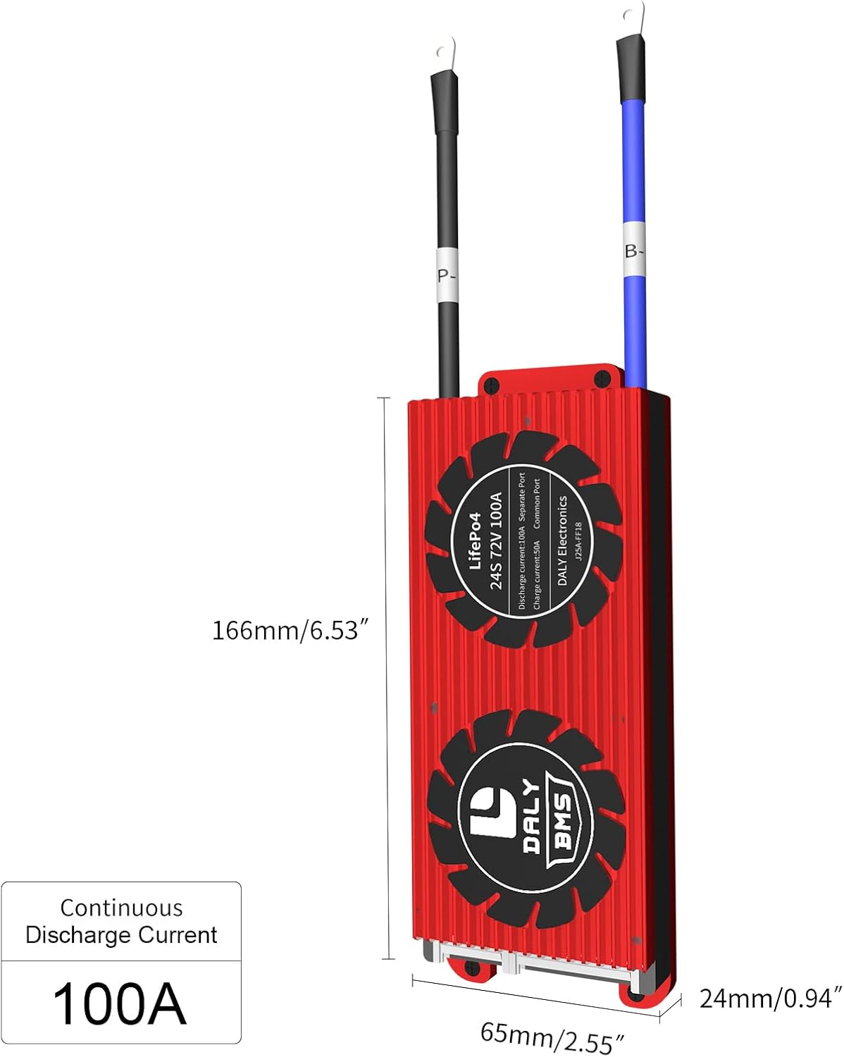
Figura 3: Physical dimensions of the DALY BMS, showing length, width, and height measurements.
8. Aplicacions
The DALY BMS is suitable for a wide range of applications utilizing LiFePO4 battery packs, including but not limited to:
- Electric scooters and E-bikes
- Electric tricycles
- Low-speed electric vehicles (EVs)
- Emergency UPS systems
- Llums solars de carrer
- RV and home energy storage systems
- Other Li-ion power battery applications
9. Garantia i Suport
DALY provides a quality guarantee for its products. For any inquiries or technical support, please refer to the following:
- Garantia de qualitat: The product is ISO/FCC/RoHS/PSE/CE approved.
- Atenció al client: DALY offers 24-hour one-on-one customer service and lifetime technical support.
- Contacte: If you require a customized BMS, bulk order, or have specific technical questions, please contact DALY customer service.
For more information or to contact support, visit the official DALY store on Amazon: DALY Official Store


