1. Introducció
The maXpeedingrods On Board Air Compressor System RS17LH is designed to provide convenient and reliable air pressure control for air spring suspension systems in trucks, pickups, and vans. This single-path system ensures even air distribution to air springs, enhancing ride comfort and maintaining proper ground clearance, especially when carrying heavy loads or towing trailers. The compact design and user-friendly controls allow for on-the-go adjustments without requiring an external air tank.
2. Contingut del paquet
Carefully unpack all components and verify that all items listed below are present and undamaged. If any items are missing or damaged, contact customer support immediately.
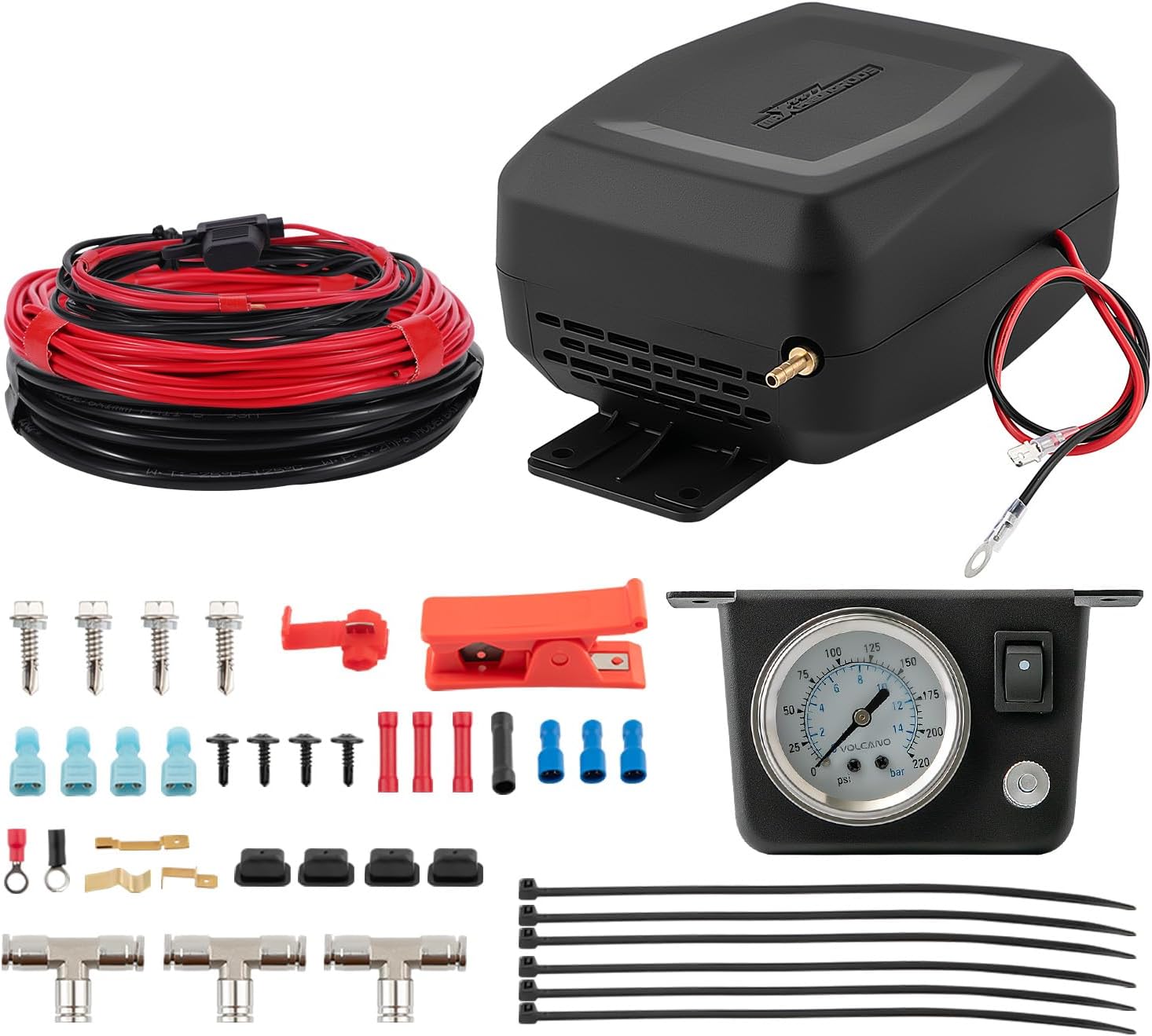
Imatge: Més deview of all included components in the maXpeedingrods On Board Air Compressor System.
- On-Board Air Compressor (with waterproof case)
- Analog Air Pressure Gauge with Dash Panel
- Air Line Tubing (6m)
- Wire Harness (2.5m black)
- Wire Harness (8.5m red)
- Fuse Harness (1m) with 15A Fuse
- T-Fittings (Stainless Steel)
- Cargols de muntatge
- Electrical Terminals and Connectors
- Tallador de línia d'aire
- Brides de cable
- Manual d'instal·lació

Image: Dimensional drawings of the compressor and gauge for installation planning.
3. Especificacions
| Característica | Especificació |
|---|---|
| Número de model | RS17LH |
| Pressió d'aire màxima | 100 psi |
| Pressió de treball recomanada | 5-70 psi |
| Interval de temperatura de funcionament | ≥ -40°F / ≤ 158°F |
| Compressor Dimensions (L x W x H) | Aproximadament 232 x 182 x 145 mm |
| Gauge Panel Dimensions (L x W x H) | Aproximadament 125 x 85 x 69 mm |
| Pes de l'article | 2.1 kg |
| Font d'alimentació | 12V DC (Vehicle Electrical System) |
| Arnès de filferro | Retardant de flama |
| Gauge Features | Backlit for visibility in all lighting conditions |

Image: Key features including flame retardant wiring, backlit gauge, and leak testing.
4. Informació de seguretat
- Desconnecteu sempre la bateria del vehicle abans de realitzar qualsevol treball elèctric.
- Assegureu-vos que totes les connexions elèctriques estiguin ben fixades i degudament aïllades per evitar curtcircuits.
- Mount the compressor in a location that is protected from direct water spray and excessive heat.
- Do not exceed the maximum recommended operating pressure of 70 psi for continuous use. The compressor has a maximum capability of 100 psi, but prolonged operation at this level is not recommended for air springs.
- Wear appropriate personal protective equipment (PPE) during installation, including safety glasses and gloves.
- Mantingueu les mans i la roba allunyades de les parts mòbils durant el funcionament.
- Ensure the air lines are routed away from hot exhaust components or sharp edges.
5. Guia d'instal·lació
This kit is designed for straightforward installation. However, professional installation is recommended if you are unfamiliar with automotive electrical or air suspension systems.
5.1. Triar una ubicació de muntatge
The compressor should be mounted in a location that is protected from road debris and direct water exposure, ideally on the vehicle's frame rail or a similar sturdy, accessible area. The dash panel with the gauge should be mounted inside the cab in a convenient location for the driver.

Image: Recommended mounting locations for the compressor and gauge.
5.2. Connexions elèctriques
- Desconnecteu el terminal negatiu de la bateria del vehicle.
- Connect the red (positive) wire from the compressor to a fused 12V power source. Use the provided fuse harness and ensure it is connected to a circuit that is only active when the ignition is on.
- Connect the black (negative) wire from the compressor to a clean, unpainted chassis ground point.
- Route the wiring for the dash panel and gauge into the cab, connecting it according to the included wiring diagram. Ensure all connections are tight and insulated.
- Install the spare 15A blade fuse into the fuse holder.

Image: The spare 15A blade fuse, crucial for protecting the compressor's electrical circuit.
5.3. Air Line Connections
Proper air line installation is critical to prevent leaks. Follow these steps carefully:

Image: Detailed tips for preventing air line leaks during installation.
- Cut the Air Tubing: Use the provided air line cutter or a sharp razor blade to make clean, square cuts. Avoid jagged or angled cuts, as these can cause leaks.
- Prepare Tubing for Fittings: If the tubing is stiff, soak it in hot water (not boiling) or use a hair dryer to soften it slightly.
- Insert into Fittings: Depress the cap on the fitting, then push the air tubing fully into the fitting until it locks. Ensure the seating ring is properly engaged.
- Route Air Lines: Route the air lines from the compressor to the air springs and to the dash gauge. Use cable ties to secure the lines, keeping them away from moving parts, sharp edges, and heat sources like the exhaust. Maintain a bending angle of less than 30 degrees to avoid kinks.
- Connect T-Fittings: Use the stainless steel T-fittings to connect the air lines to the air springs, ensuring a snug fit.
- Comproveu si hi ha fuites: After all connections are made, re-connect the battery. Inflate the air springs to the recommended pressure and spray all connections with a soapy water solution. Look for bubbles, which indicate a leak. Tighten or re-seat connections as necessary.

Image: Installation of the compressor under a vehicle.
6. Instruccions de funcionament
Once installed, the maXpeedingrods air compressor system allows for easy adjustment of your air springs from inside the vehicle.

Image: Convenient control of air pressure from the driver's seat using the dash gauge.
- Turn on the System: Locate the switch on the dash panel and turn it to the 'ON' position. The compressor will begin to operate.
- Monitor de pressió: Observe the analog gauge on the dash panel. It displays the current air pressure in your air springs. The gauge is backlit for clear visibility in various lighting conditions.
- Ajust de pressió: Allow the compressor to run until the desired air pressure is reached. The recommended working pressure range is 5-70 psi. Do not exceed 70 psi for normal operation.
- Turn off the System: Once the desired pressure is achieved, turn the switch on the dash panel to the 'OFF' position.
This single-path system ensures that air pressure is distributed equally to both air springs, providing balanced support for your vehicle.

Image: Illustration of the single path system distributing air evenly to both air springs.
7. Manteniment
- Inspecció periòdica: Periodically inspect all air lines and connections for signs of wear, damage, or leaks. Check electrical wiring for fraying or loose connections.
- Compressor Cleaning: Keep the compressor unit clean and free of excessive dirt or debris. The waterproof case provides protection, but regular cleaning helps maintain performance.
- Comprovació de fusibles: If the compressor fails to operate, check the 15A fuse in the fuse harness. Replace it with a new 15A fuse if blown.
- Entorn de funcionament: The system is designed to operate in a wide temperature range (≥ -40°F / ≤ 158°F). Ensure the compressor is not exposed to temperatures outside this range for prolonged periods.

Image: The onboard air compressor with its waterproof casing, dissenyat per a la durabilitat.
8. Solució De Problemes
| Problema | Causa possible | Solució |
|---|---|---|
| El compressor no s'engega. | No power to the compressor; Blown fuse; Loose electrical connection. | Check the dash panel switch. Verify 12V power at the compressor. Inspect and replace the 15A fuse if blown. Check all electrical connections for tightness. |
| Air springs do not inflate or lose pressure quickly. | Air leak in the system; Damaged air line or fitting; Faulty air spring. | Perform a leak test using soapy water on all connections and air springs. Tighten loose fittings. Replace damaged air lines or fittings. Inspect air springs for damage. |
| Compressor runs but air pressure does not increase. | Major air leak; Compressor malfunction. | Check for significant air leaks. If no leaks are found and the compressor is running, contact customer support. |
| Gauge reads incorrectly. | Gauge malfunction; Air line blockage to gauge. | Verify air line connection to the gauge. If problem persists, contact customer support. |
9. Garantia i atenció al client
maXpeedingrods warrants its products to the original retail purchaser against manufacturing defects under normal use for 1 any des de la data de compra. Aquesta garantia cobreix els defectes de materials i de fabricació.
For technical support, warranty claims, or any questions regarding your maXpeedingrods On Board Air Compressor System, please contact maXpeedingrods customer service. Lifetime technical support is provided.
Contact information can typically be found on the maXpeedingrods official weblloc web o a través de la vostra plataforma de compra.


