1. Introducció
This manual provides detailed instructions for the installation, operation, and maintenance of the Beninca Telescopic Sliding Gate System Hardware. This kit is designed for two-door gate systems, accommodating an opening of 17 feet 6 inches, suitable for a total gate size of 21 feet. Please read this manual thoroughly before beginning installation to ensure proper setup and safe operation.

Figure 1: Assembled Telescopic Sliding Gate System
Figure 1 illustrates a fully assembled telescopic sliding gate system, demonstrating the two gate panels in their closed position. This system allows for efficient and compact gate operation, ideal for various property types.
2. Pautes de seguretat
Adherence to safety precautions is critical during installation, operation, and maintenance of the gate system. Failure to follow these guidelines may result in property damage, serious injury, or death.
- Always wear appropriate personal protective equipment (PPE) including safety glasses, gloves, and sturdy footwear during installation.
- Ensure all electrical connections, if applicable, are performed by a qualified electrician and comply with local codes.
- Keep hands, clothing, and tools clear of moving parts during operation and testing.
- Do not allow children to play near the gate or operate the gate controls.
- Regularly inspect the gate system for signs of wear, damage, or misalignment.
- Disconnect power to any gate opener before performing maintenance or repairs.
3. Contingut del paquet
Verify that all components listed below are present and undamaged before beginning installation. Refer to Figure 2 for a visual representation of the kit components.
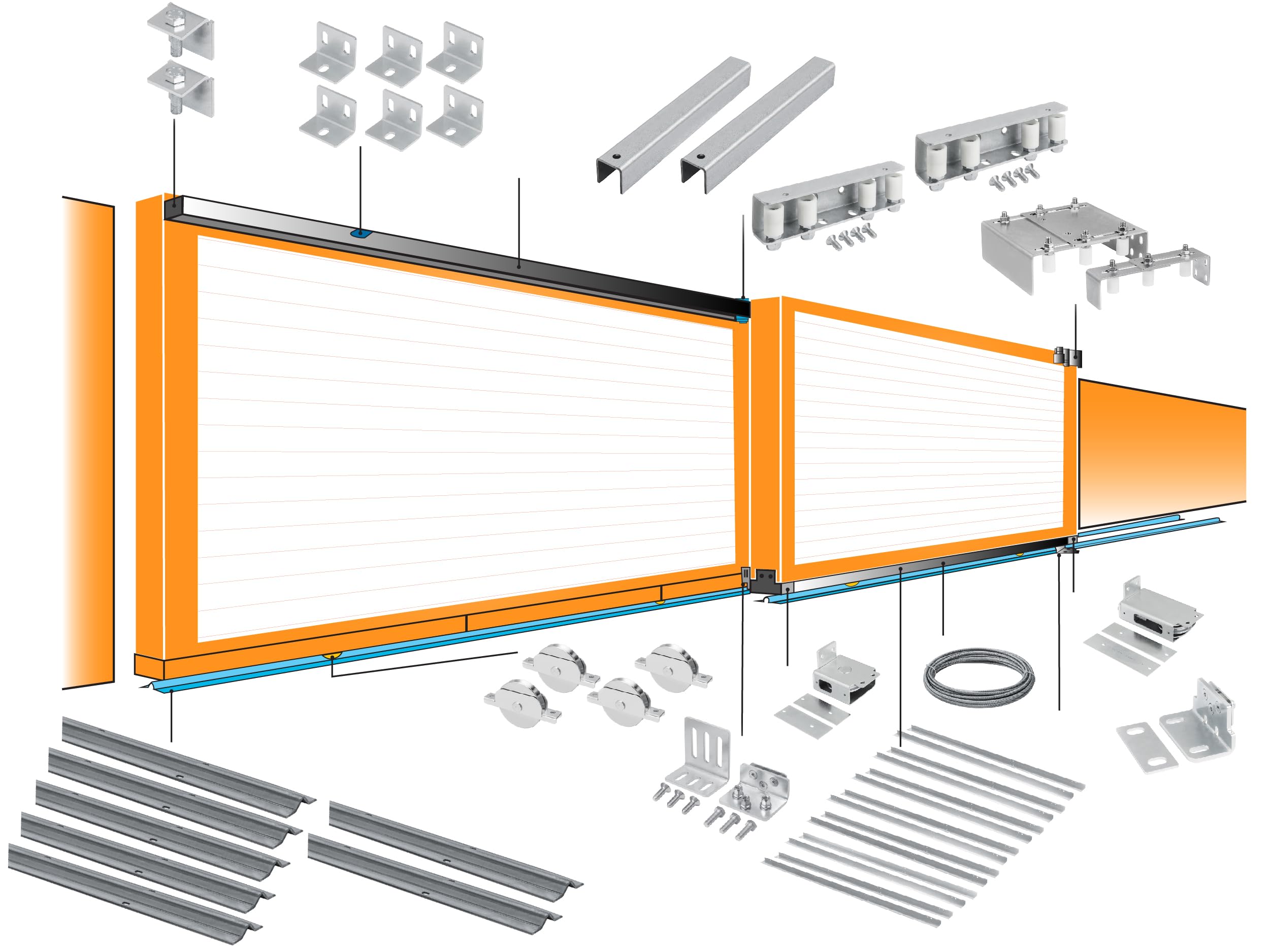
Figura 2: Explotat View of Kit Components
Figure 2 provides an exploded diagram of the Beninca Telescopic Sliding Gate System hardware, illustrating each component and its corresponding part number for easy identification during assembly.
Included Components List:
- 6 x 281.11 Galvanized Cable Covers (38x20x1.5 L 1200 MM / 4Ft)
- 1 x 282.501 Galvanized Fixed Pulley Box for 5MM Cable
- 1 x 282.511 Galvanized Movable Pulley Box for 5MM Cable
- 1 x 282.521 Galvanized Cable Ground Fixing Bracket
- 1 x 282.531 Galvanized Connection Gate Bracket Between Panels
- 7 x 283.011 Galvanized L-Bracket (42x40x3 for U-Track 283.3xx)
- 2 x 283.013 Galvanized Track Cap
- 2 x 283.323 Galvanized U-Track (38x38x3 for ø 30 MM Rollers 6 FT)
- 2 x 283.302 Galvanized Guide Bracket with 4 30MM Nylon Rollers
- 1 x 283.201 Adjustable Guide Plate with 3 Rollers
- 4 x 109.120T Galvanized Wheel with Internal Support, V Groove, 1 Bearing
- 30 ft x 284.503 Stainless Steel 5MM Cable
- 7 x V Track Italy (6ft sections)
4. Configuració i instal·lació
Proper installation is crucial for the functionality and longevity of your telescopic gate system. Follow these steps carefully.
4.1 Gate Frame Preparation
Ensure your gate frames are constructed to the recommended specifications for optimal performance and stability.

Figure 3: Recommended Gate Frame Dimensions and Overlap
Figure 3 illustrates the recommended dimensions for the gate frame: 3 inches wide by 6 inches high. It also details the minimum overlapping 'S' distance, which should be 18 inches for small gates and 36 inches for larger gates (for 2-door guides). The table provides recommended values for A (mm), S (mm), and T (mm) based on gate size.
- Recommended Frame Size: 3 inches wide x 6 inches height.
- Minimum Overlapping (S): 18 inches for small gates, 36 inches for larger gates (for 2-door guides).
- Recommended Frame Thickness (T): 3 inches for better stability and to match pulley box width.
4.2 Component Layout and Assembly
Refer to Figure 4 for the general layout of components on the gate panels. This diagram helps in understanding the placement of each part.

Figure 4: Components Layout
Figure 4 illustrates the strategic placement of various components on the two gate panels. Key components shown include the End Cap (7), U-Channel Bracket (6), U Channel (8), Door Roller Guide (9), Top Roller Guide (10), Adjustable Pulley (3), Cable Cover (1), Pulley (2), Door Bracket (5), Floor Bracket (4), Cable (12), and Recessed Wheel (11) along with V-Tracks.
4.3 Track and Wheel Installation
- Install the V-Tracks (7 sections of 6ft) along the gate's path on the ground. Ensure they are level and securely anchored.
- Attach the 109.120T Galvanized Wheels (4 units) with internal support and V-groove to the bottom of the gate panels. These wheels will run along the V-Tracks.
- Mount the 283.323 Galvanized U-Tracks (2 units, 6 FT each) to the top of the gate structure.
- Secure the 283.011 Galvanized L-Brackets (7 units) to support the U-Tracks.
- Install the 283.013 Galvanized Track Caps (2 units) at the ends of the U-Tracks.
4.4 Cable System Assembly
- Attach the 282.501 Galvanized Fixed Pulley Box and 282.511 Galvanized Movable Pulley Box for the 5MM cable.
- Secure the 282.521 Galvanized Cable Ground Fixing Bracket to the ground near the gate's opening.
- Install the 282.531 Galvanized Connection Gate Bracket between the gate panels to facilitate cable routing.
- Route the 30 ft of 284.503 Stainless Steel 5MM Cable through the pulley boxes and brackets as per the system design, ensuring proper tension.
- Install the 281.11 Galvanized Cable Covers (6 units) to protect the cables.
4.5 Guide Bracket Installation
- Mount the 283.302 Galvanized Guide Brackets (2 units) with 4 30MM Nylon Rollers to the gate structure to guide the gate panels smoothly.
- Install the 283.201 Adjustable Guide Plate with 3 Rollers, ensuring it is fixed securely and allows for smooth gate movement.
4.6 Calculating Gate Length (LA)
For a 2-panel system, the length of each door (LA) is calculated based on the total opening and the overlapping (S) distance.

Figure 5: LA Calculation for 2-Panel System
Figure 5 provides the formula for calculating the length of each door (LA) in a 2-panel system: LA = (Opening / 2) + Overlapping (S). This calculation is essential for ensuring the gates operate correctly and fully cover the opening.
Fórmula: LA (each door length) = (Opening / 2) + Overlapping (S)
Ensure your gate panels are cut and assembled to these precise measurements for optimal functionality.
5. Instruccions de funcionament
This hardware kit provides the mechanical components for a telescopic sliding gate system. The operation of the gate will depend on the specific gate opener (motor) chosen and installed separately. This section describes the general mechanical operation.
- When activated, the primary gate panel (Door 1) will begin to slide.
- The cable system, connected to the fixed and movable pulleys, will simultaneously pull the secondary gate panel (Door 2) at a proportional speed, causing it to extend or retract in conjunction with Door 1.
- The V-groove wheels running on the V-tracks ensure smooth horizontal movement, while the guide brackets and rollers maintain vertical stability and alignment.
- Ensure the gate path is clear of obstructions before and during operation.
6. Manteniment
Regular maintenance ensures the longevity and reliable operation of your Beninca telescopic gate system.
- Inspecció mensual: Check all moving parts, including wheels, pulleys, and cables, for signs of wear, damage, or corrosion.
- Lubricació: Apply a suitable lubricant to the wheels, pulleys, and any other friction points every 3-6 months, or more frequently in harsh environments.
- Neteja: Keep the V-tracks and U-tracks free from dirt, debris, leaves, and ice. Clean the gate panels and hardware regularly to prevent buildup.
- Tensió del cable: Periodically check the tension of the 5MM stainless steel cable. Adjust if necessary to ensure smooth and synchronized gate movement.
- Comprovació de fixació: Verify that all bolts, screws, and fasteners are tight. Retighten any loose connections.
7. Solució De Problemes
This section addresses common issues that may arise with the mechanical components of the telescopic gate system.
| Problema | Causa possible | Solució |
|---|---|---|
| Gate movement is stiff or jerky | Dirty or obstructed tracks; lack of lubrication; worn wheels/pulleys. | Clean tracks thoroughly. Lubricate wheels and pulleys. Inspect for damaged components and replace if necessary. |
| Gate panels do not synchronize | Incorrect cable tension; cable slippage; damaged pulley. | Check and adjust cable tension. Ensure cable is properly seated in pulleys. Inspect pulleys for damage. |
| Soroll excessiu durant el funcionament | Lack of lubrication; loose fasteners; worn components. | Lubricate all moving parts. Tighten all fasteners. Replace any worn wheels or bearings. |
| Gate panels rub against each other or guides | Misaligned guide brackets; bent gate frame; improper overlap. | Adjust guide brackets for proper clearance. Inspect gate frames for straightness. Re-evaluate overlap (S) as per Section 4.1. |
8. Especificacions
- Número de model: Telescopic Full Kit for Opening 17'6"
- Fabricant: Beninca Hi-Motions
- Material: Acer galvanitzat
- Color: Plata
- Pes de l'article: Aproximadament 150 lliures (68 kg)
- Dimensions del producte: 62 x 9 x 62 polzades (envasat)
- Gate Opening Capacity: 17 peus 6 polzades
- Gate Size Supported: Up to 21 feet (total)
- Tipus de cable: 5MM Stainless Steel
- Diàmetre del rodet: 30 MM Nylon Rollers
9. Garantia i Suport
For warranty information, technical support, or to purchase replacement parts, please contact Beninca customer service or your authorized dealer. Keep your purchase receipt and model information handy when contacting support.


