1. Introducció
The Ortis In-Wall Humidity Sensor Switch is an advanced control system designed to automatically manage ventilation in environments prone to high humidity, such as bathrooms, basements, and laundry rooms. It features a main in-wall switch unit and a separate, wireless humidity sensor, allowing for flexible placement and precise moisture detection. This system helps prevent issues like mildew, odors, and structural damage by maintaining optimal humidity levels.

Figure 1.1: Ortis Humidity Sensor Switch and Wireless Sensor
This image displays the main in-wall humidity sensor switch unit on the left, featuring an LCD screen and control buttons. To the right is the separate, black wireless humidity sensor unit, designed for remote placement.
2. Informació de seguretat
WARNING: Risk of Electric Shock. Installation requires working with high voltage. Always turn off power at the circuit breaker before installation, inspection, or removal. If you are unsure about any part of the installation process, consult a qualified electrician.
- This device requires a neutral wire for proper operation. Ensure your electrical box has a neutral wire available.
- Do not install with wet hands or while standing on wet surfaces.
- Assegureu-vos que totes les connexions dels cables estiguin segures i correctament aïllades.
- Operar dins del volum especificattage range (110/220V).
3. Contingut del paquet
- Ortis In-Wall Humidity Sensor Switch (Main Unit)
- Ortis Wireless Humidity Sensor (Separate Unit)
- Cargols de muntatge
- Filferro
- Manual d'usuari (aquest document)
4. Especificacions del producte
| Característica | Especificació |
|---|---|
| Número de model | KJ-047 |
| Marca | Ortis |
| Product Dimensions (Switch) | 4.5 x 2.1 x 2.1 polzades |
| Dimensions del producte (sensor) | 5.6 x 2.1 x 1.5 polzades |
| Vol. Operatiutage | 110/220V |
| abast sense fils | Fins a 328 peus (100 metres) |
| Mode d'operació | Automatic-Manual |
| Tipus de muntatge | Muntatge de paret |
| Tipus de contacte | Normalment obert |
| Material | Metall (material de contacte) |

Figura 4.1: Dimensions del producte
This image provides a visual representation of the dimensions for both the in-wall switch unit and the separate wireless sensor unit, showing measurements in inches.
5. Instal·lació i configuració
5.1 Wiring the Switch
Before beginning, ensure power is OFF at the circuit breaker.
- Identify the Line (Hot), Load (Fan), Neutral, and Ground wires in your electrical box.
- Connect the white wire from the switch to the neutral wire from the electrical box using a wire nut.
- Connect the black wire from the switch to the Line (Hot) wire from the electrical box.
- Connect the blue wire from the switch to the Load (Fan) wire.
- Connect the ground wire from the switch (if present) to the electrical box ground wire.
- Carefully push the wires into the electrical box and secure the switch with screws.

Figure 5.1: Easy Wiring Diagram (120VAC)
This diagram illustrates the wiring connections for the Ortis Humidity Sensor Switch, showing connections for 120VAC, including Line (Black), Neutral (White), and Load (Blue) wires to the fan. A neutral wire is required.
5.2 Sensor Battery Installation
The wireless sensor requires batteries (typically AAA, not always included). Open the sensor casing, insert the batteries according to polarity markings, and close the casing de manera segura.
5.3 Pairing the Sensor with the Controller
The sensor and controller must be paired for automatic operation.
- On the main switch unit, press and hold the 'M' button for approximately 3 seconds.
- The pairing icon (often a flashing signal or antenna symbol) will appear on the LCD screen, indicating the switch is in pairing mode.
- On the wireless sensor unit, locate the small pairing button inside the battery compartment or on the circuit board. Press this button briefly.
- The pairing icon on the switch's LCD screen should stop flashing and become solid, indicating successful pairing.

Figure 5.2: How to Pair the Sensor with the Controller
This image illustrates the three steps for pairing the wireless sensor with the main controller: 1. Press and hold the 'M' button on the controller for 3 seconds. 2. Observe the flashing icon on the controller's screen. 3. Press the button inside the sensor to complete pairing.
5.4 Col·locació del sensor
Place the wireless sensor in an optimal location for humidity detection. For bathrooms, this is typically away from direct shower spray but within the area where humidity accumulates. For basements or laundry rooms, place it where moisture is most prevalent. The sensor has a range of up to 328 ft from the main switch.
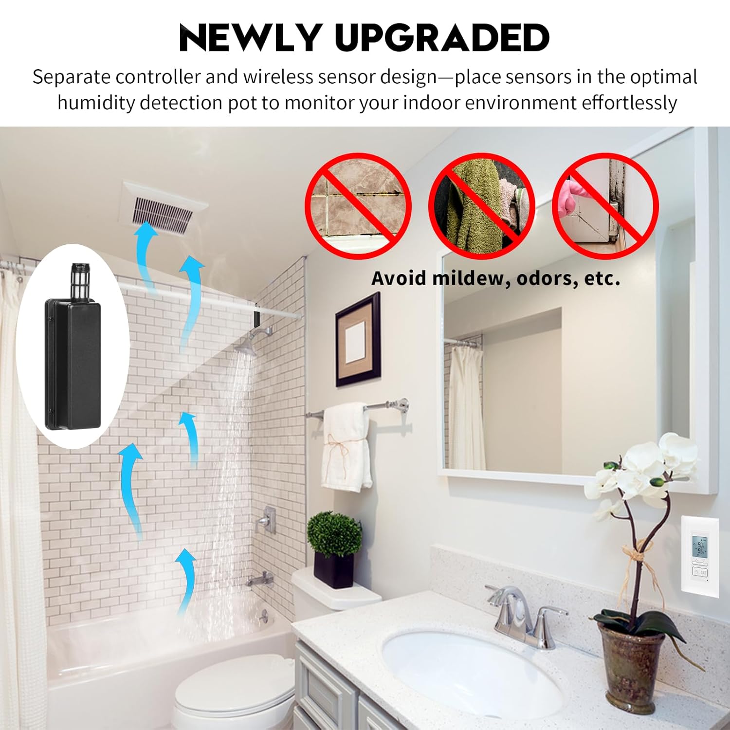
Figure 5.3: Sensor Placement for Optimal Humidity Detection
This image demonstrates the concept of placing the separate wireless sensor in an optimal location to monitor the indoor environment, showing air circulation and the benefit of avoiding mildew and odors.
6. Instruccions de funcionament
The Ortis Humidity Sensor Switch offers both automatic and manual operation modes.
6.1 Mode automàtic
In Automatic Mode, the switch will activate the connected fan when the detected humidity level exceeds your set threshold and deactivate it when the humidity drops below the threshold. This mode utilizes digital sensing technology for efficient ventilation.

Figure 6.1: Auto Mode Operation
This image highlights the 'AUTO MODE' feature of the switch, emphasizing digital sensing technology, automatic ventilation, and the benefit of keeping the room dry.
6.2 Mode manual
Press the 'M' button to switch to Manual Mode. In this mode, you can manually turn the fan ON or OFF using the control buttons, overriding the automatic humidity detection. This is useful for situations where you need continuous ventilation or prefer to control the fan directly.

Figure 6.2: Manual Mode for Quiet Operation
This image illustrates the benefit of Manual Mode, allowing users to operate the fan switch manually to ensure a quiet sleep environment by avoiding automatic fan activation during the night.
6.3 Configuració dels nivells d'humitat
Use the Up and Down arrow buttons on the switch to adjust the desired humidity set point. The fan will activate when the ambient humidity rises above this set point and turn off when it falls below.

Figure 6.3: LCD Display with Humidity Settings
This image shows a close-up of the switch's LCD screen, displaying the current humidity percentage (%RH) and the user-set humidity threshold.
6.4 Funció de bloqueig de tecles
To prevent accidental changes to settings, the switch features a key lock function. Consult the on-screen prompts or specific button combinations (often pressing and holding two buttons simultaneously) to activate or deactivate the key lock.

Figure 6.4: Key Lock Feature
This image highlights the key lock icon on the switch's display and a hand interacting with the buttons, indicating the activation or deactivation of the key lock function.
7. Manteniment
7.1 Neteja
To clean the switch and sensor, gently wipe the surfaces with a soft, dry cloth. Do not use abrasive cleaners, solvents, or excessive moisture, as this may damage the electronic components.
7.2 Sensor Battery Replacement
When the sensor's battery indicator on the main switch unit shows low power, replace the batteries in the wireless sensor unit. Open the battery compartment, remove old batteries, and insert new ones, ensuring correct polarity. Dispose of old batteries responsibly.
8. Solució De Problemes
| Problema | Causa possible | Solució |
|---|---|---|
| Fan does not turn on in Auto Mode. | Humidity level is below set point. Incorrect wiring. Sensor not paired or low battery. | Check current humidity vs. set point. Verify wiring connections. Re-pair sensor or replace sensor batteries. |
| Sensor not pairing. | Sensor too far from switch. Low sensor battery. Incorrect pairing procedure. | Move sensor closer to switch. Replace sensor batteries. Follow pairing steps carefully (Section 5.3). |
| Lectures d'humitat inexactes. | Sensor placed in an unsuitable location (e.g., near heat source, direct water spray). Sensor dirty. | Relocate sensor to a more representative area. Gently clean sensor vents. |
| Switch display is blank. | No hi ha alimentació a l'interruptor. | Check circuit breaker. Verify wiring connections. |

Figure 8.1: Solving Common Humidity-Related Problems
This image illustrates how the Ortis Humidity Sensor Switch addresses common issues like loud fan noise, bathroom odor, and mildew, by providing noise-free operation, improved air quality, and reduced humidity.
9. Garantia i Suport
Ortis products are designed for reliability and performance. This product comes with a standard manufacturer's warranty. For detailed warranty information, technical support, or service inquiries, please refer to the contact information provided on the product packaging or the official Ortis website. Please have your model number (KJ-047) and purchase date available when contacting support.


