1. Introducció
This manual provides detailed instructions for the assembly, operation, and maintenance of your POWERTEC Flip Top Tool Stand with Caster Wheels, Model UT1012. This mobile workbench is designed to enhance your workshop efficiency by allowing you to mount two benchtop power tools and switch between them effortlessly. Please read this manual thoroughly before assembly and operation to ensure safe and correct usage.

Image 1.1: The POWERTEC Flip Top Tool Stand with Caster Wheels (UT1012).
This image displays the complete POWERTEC Flip Top Tool Stand, featuring its black frame, yellow accents, and white tabletop. The stand is equipped with caster wheels for mobility and a red handle for the flip-top mechanism.
2. Informació de seguretat
Always observe basic safety precautions when using this tool stand to reduce the risk of personal injury or damage to the product. Keep this manual for future reference.
- Llegeix les instruccions: Read and understand all instructions before assembling or operating the tool stand.
- Capacitat de pes: Do not exceed the maximum weight capacity of 300 lbs (136 kg). Overloading can cause instability and damage.
- Superfície estable: Always operate the stand on a level, stable surface.
- Secure Tools: Ensure all mounted tools are securely fastened to the tabletop before operation or flipping.
- Rodes de bloqueig: Always engage the foot pedal lock to stabilize the stand before operating any mounted tools.
- Àrea clara: Keep the work area clear of obstructions and ensure sufficient space for flipping the tabletop.
- Equips de protecció individual (EPI): Wear appropriate safety gear, such as safety glasses, when operating power tools mounted on the stand.
- Infants i espectadors: Mantenir els nens i els espectadors allunyats de la zona de treball.
3. Llista de components
Before beginning assembly, verify that all components are present and undamaged. If any parts are missing or damaged, contact POWERTEC customer support.
- Main Frame Components (Vertical and Horizontal Supports)
- Flip Top Tabletop Assembly
- Caster Wheels (2 fixed, 1 swivel with foot pedal)
- Red Handle Mechanism
- Hardware (Bolts, Nuts, Washers, Wrenches)
- Manual d'instruccions
4. Instruccions de muntatge
Follow these steps carefully to assemble your POWERTEC Flip Top Tool Stand.
- Desempaquetar components: Carefully remove all parts from the packaging. Lay them out on a clean, flat surface to identify each component.
- Muntar el marc base: Connect the horizontal and vertical frame components using the provided hardware. Ensure all bolts are finger-tightened initially.
- Fixeu les rodes giratòries: Secure the two fixed caster wheels to one end of the base frame and the swivel caster with the foot pedal mechanism to the opposite end. Ensure the foot pedal is accessible.
- Install Tabletop Supports: Attach the tabletop support brackets to the vertical frame components.
- Mount Flip Top Assembly: Carefully position the flip-top tabletop assembly onto the support brackets. Secure it using the designated pivot points and hardware.
- Install Red Handle: Attach the red handle mechanism to the side of the tabletop assembly. This handle is used to release and lock the tabletop rotation.
- Ajustament final: Once all components are in place, systematically tighten all bolts and nuts securely. Do not overtighten.

Image 4.1: An assembled POWERTEC Flip Top Tool Stand with a planer mounted on the top surface.
This image illustrates the fully assembled tool stand with a benchtop planer securely attached to one side of the flip-top surface, ready for use.
5. Funcionament
5.1 Eines de muntatge
The stand is designed to accommodate two benchtop tools. Ensure your tools fit within the tabletop dimensions (25" x 20.6") and do not exceed the maximum tool height of 23-3/16" when flipped.
- Position Tools: Place your desired benchtop tools on each side of the flip-top tabletop.
- Marqueu els forats de muntatge: Use the tool's base to mark the mounting hole locations on the tabletop.
- Forats: Carefully drill appropriate-sized holes through the tabletop for your tool's mounting hardware.
- Secure Tools: Use bolts, washers, and nuts (not included) to securely fasten each tool to its respective side of the tabletop. Ensure all fasteners are tight before use.

Image 5.1: The tool stand with a planer mounted and flipped to the underside.
This image shows a benchtop planer securely mounted to one side of the flip-top tabletop, which is currently rotated downwards, making the other side of the tabletop accessible for a second tool.
5.2 Flipping the Tabletop
To switch between mounted tools:
- Desbloquejar: Locate the red handle on the side of the tabletop assembly. Pull the handle outwards to disengage the locking mechanism.
- Girar: Carefully rotate the tabletop 180 degrees until the desired tool is facing upwards.
- Bloqueig: Release the red handle. Ensure it fully engages and locks the tabletop securely in place. You should hear an audible click. Verify the tabletop is stable before operating any tools.

Imatge 5.2: Primer pla view of the red handle mechanism.
This image highlights the red handle, which is pulled to unlock the flip-top mechanism, allowing the tabletop to rotate and switch between mounted tools.
5.3 Mobilitat i estabilitat
The stand features two fixed casters and one foot-activated swivel caster for easy movement and secure positioning.
- Moure el suport: To move the stand, ensure the foot pedal is in the "up" position, allowing the swivel caster to engage. Push or pull the stand to your desired location.
- Fixació del suport: To stabilize the stand for operation, press down firmly on the foot pedal. This will lift the fixed casters slightly and engage the swivel caster's brake, preventing movement.

Image 5.3: A user operating the foot pedal for mobility.
This image shows a foot pressing down on the pedal, which activates the swivel caster's locking mechanism, securing the stand in place for stable operation.
6. Manteniment
Regular maintenance ensures the longevity and safe operation of your tool stand.
- Inspeccionar els elements de fixació: Periodically check all bolts, nuts, and other fasteners for tightness. Tighten as necessary.
- Superfícies netes: Wipe down the frame and tabletop with a damp cloth to remove dust and debris. Avoid harsh chemicals that may damage the finish.
- Inspecció de rodes: Check caster wheels for wear, damage, or accumulation of debris. Clean as needed to ensure smooth rolling.
- Mecanisme de volteig: Ensure the flip mechanism operates smoothly. If it becomes stiff, a light application of lubricant to the pivot points may be beneficial.
7. Solució De Problemes
Consulteu aquesta secció per conèixer els problemes comuns i les seves solucions.
| Problema | Causa possible | Solució |
|---|---|---|
| El suport és inestable o trontolla. | Loose fasteners; uneven floor; foot pedal not engaged. | Tighten all assembly bolts. Move stand to a level surface. Ensure foot pedal is fully pressed down to lock the swivel caster. |
| Tabletop does not flip smoothly. | Red handle not fully disengaged; pivot points require lubrication; obstruction. | Ensure red handle is pulled out completely. Apply a light lubricant to the pivot points. Check for any debris obstructing rotation. |
| Caster wheels do not roll freely. | Debris in wheels; damaged casters. | Clean any debris from around the caster wheels. If casters are damaged, contact customer support for replacements. |
| Mounted tool feels loose. | Tool mounting hardware is loose. | Tighten all bolts and nuts securing the tool to the tabletop. |
8. Especificacions
Technical specifications for the POWERTEC Flip Top Tool Stand (UT1012).
| Número de model: | UT1012 |
| Marca: | POWERTEC |
| Material: | Acer d'aliatge |
| Tipus d'acabat: | Recobert de pols |
| Capacitat de pes: | 300 lliures (136 kg) |
| Dimensions de la taula: | 63.5 cm x 52.3 cm |
| Alçada total: | 30.5 polzades (77.5 cm) |
| Max Tool Height (Flipped): | 58.9 cm (23-3/16") |
| Item Weight (Unassembled): | 48.4 lliures (21.95 kg) |
| Característiques especials: | Portable, Wheels, Flip-Top Design |
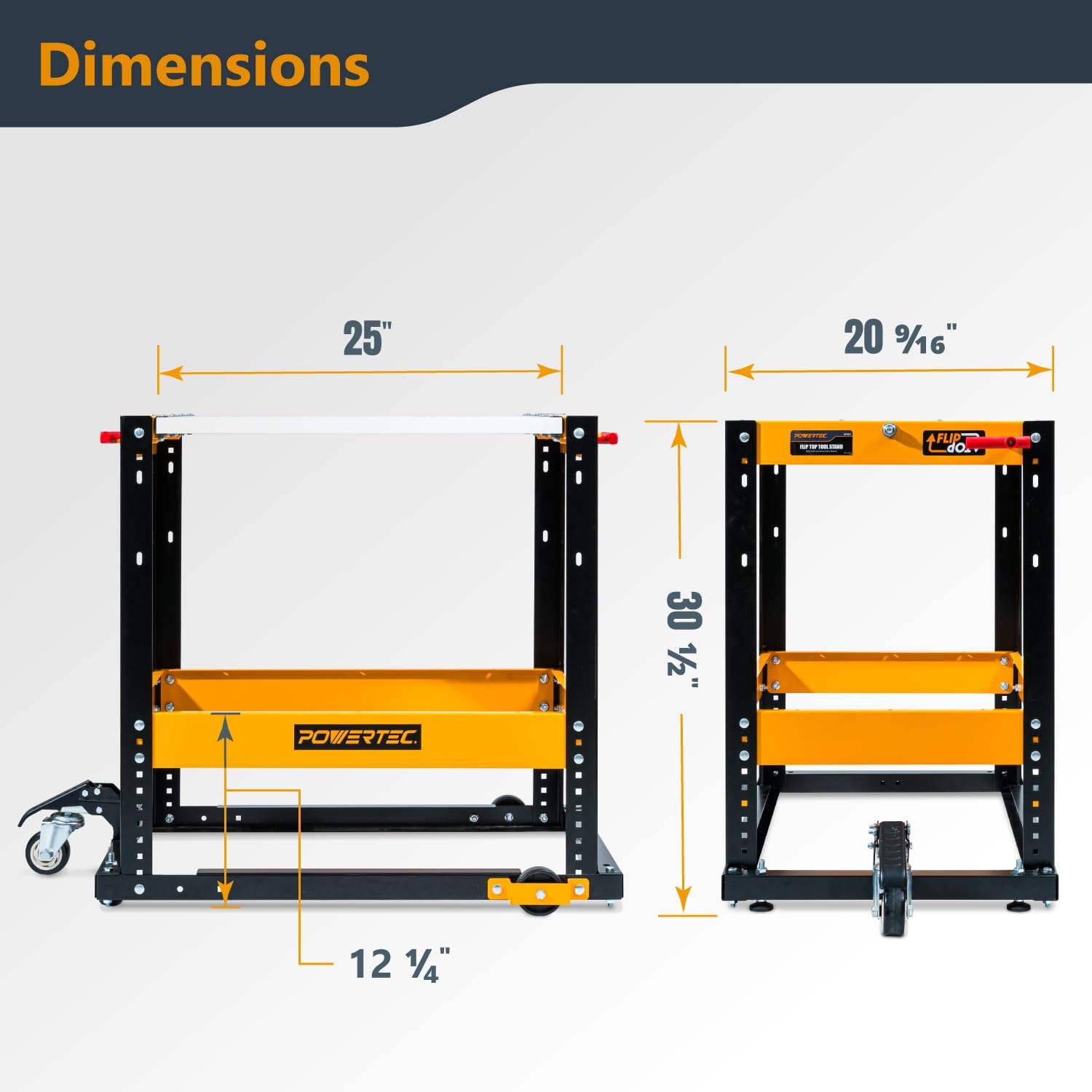
Image 8.1: Dimensional drawing of the POWERTEC Flip Top Tool Stand.
This diagram illustrates the key dimensions of the tool stand, including its height, tabletop width, and depth, providing essential information for planning tool placement.
9. Informació de la garantia
POWERTEC products are manufactured to high-quality standards. This product is covered by a limited warranty against defects in materials and workmanship. For specific warranty terms and conditions, please refer to the warranty card included with your product or visit the official POWERTEC weblloc.
10. Atenció al client
If you have any questions, require assistance with assembly, or need to report a missing or damaged part, please contact POWERTEC customer support:
- Weblloc: www.powertecproducts.com
- Correu electrònic: Consulteu weblloc web per a formulari de contacte o adreça de correu electrònic.
- Telèfon: Consulteu website for customer service phone number.
Please have your model number (UT1012) and purchase information ready when contacting support.


