1. Introducció
This manual provides detailed instructions for the installation, operation, and maintenance of the System Sensor P2GRKLED L-Series Outdoor Compact Wall-Mounted Horn Strobe. This device is designed for use in fire alarm and emergency signaling systems, providing both audible and visual alerts. Please read this manual thoroughly before installation and operation to ensure proper functionality and safety.
2. Informació de seguretat
Installation and wiring of this device must be performed by qualified personnel in accordance with all local and national electrical codes, as well as the National Fire Protection Association (NFPA) standards. Failure to follow these instructions may result in property damage, serious injury, or death.
- Desconnecteu sempre l'alimentació abans d'instal·lar, revisar o desmuntar el dispositiu.
- Ensure all wiring connections are secure and comply with wiring diagrams.
- No excedeixi el vol especificattage i qualificacions actuals.
- This device is intended for outdoor use and is rated NEMA 4X and IP56. Ensure proper sealing and mounting to maintain its weatherproof integrity.
- Test the device after installation to confirm proper operation.
3. Producte acabatview i Característiques
The System Sensor P2GRKLED is an L-Series outdoor compact wall-mounted horn strobe designed for reliable fire alarm notification. It features advanced LED technology for the strobe, offering improved efficiency and reduced power consumption.
Característiques principals:
- Reduced Current Draw: Approximately 60% lower current draw compared to previous generations, allowing more devices per Notification Appliance Circuit (NAC).
- Resistència a la intempèrie: NEMA 4X and IP56 rated as a standalone device, suitable for harsh outdoor environments without additional backbox sealing.
- Compatibilitat: Designed for compatibility with legacy System Sensor SpectrAlert, SpectrAlert Advance, and L-Series notification appliances for retrofit applications.
- Certificacions: Dual-listed with both UL and ULC certifications.
- Versatile Candela Settings: Supports a full range of candela settings for various application requirements.
- Opcions de muntatge: Supports wall-mount installations.
- Disseny compacte: Features a compact size for wall-mount devices.
- Tecnologia LED: Utilizes common LED lenses for efficient visual signaling.

Figura 1: lateral view of the System Sensor P2GRKLED L-Series Outdoor Horn Strobe, showing its compact red housing and the 'FIRE' label.
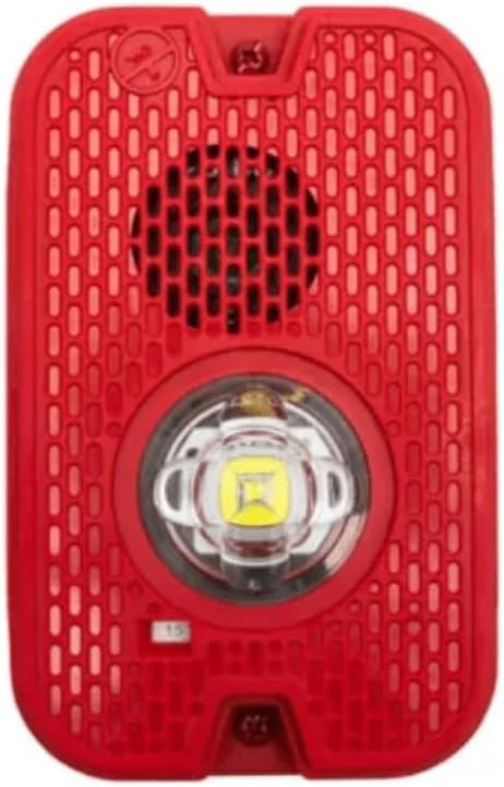
Figura 2: Frontal view of the System Sensor P2GRKLED L-Series Outdoor Horn Strobe, highlighting the horn grille and the central LED strobe light.
4. Contingut del paquet
Verifiqueu que tots els components siguin presents abans de començar la instal·lació:
- System Sensor P2GRKLED L-Series Outdoor Horn Strobe (1 unit)
5. Especificacions
| Atribut | Especificació |
|---|---|
| Número de model | P2GRKLED |
| Marca | Sensor del sistema |
| Color | Vermell |
| Forma | Rectangular |
| Tipus d'acabat | Pintat |
| Tipus de font de llum | Díode emissor de llum (LED) |
| Font d'alimentació | Elèctric amb cable |
| Pes de l'article | 2 lliures (0.91 kg) |
| Estil | Compacte |
| Tipus de muntatge | Muntatge de paret |
| Dimensions del producte | 12.7 cm de llargada x 12.7 cm d'amplada x 12.7 cm d'alçada |
| Classificació resistent a la intempèrie | NEMA 4X, IP56 |
| UPC | 783863060038 |
6. Configuració i instal·lació
Proper installation is crucial for the reliable operation of the horn strobe. Refer to the specific installation instructions provided with the product packaging for detailed diagrams and wiring schematics. The following is a general guide.
6.1 Muntatge
- Seleccioneu la ubicació: Choose a wall-mount location that complies with local codes and provides optimal visibility and audibility. Ensure the surface is flat and secure.
- Prepare Mounting Box: Install a suitable electrical box (e.g., a 4-inch square box with an extension ring, or a weather-resistant outdoor box) according to local codes.
- Col·loqueu la placa de muntatge: Secure the device's mounting plate to the electrical box. Ensure the plate is oriented correctly for the desired device position.
- Segellat meteorològic: As the device is NEMA 4X and IP56 rated, additional caulk or sealant on the backbox is generally not required, simplifying installation. However, ensure the mounting surface is flush and the device gasket creates a proper seal.
6.2 Cablejat
- Desconnecteu l'alimentació: Ensure all power to the Notification Appliance Circuit (NAC) is disconnected before wiring.
- Connecteu els cables: Route the NAC wiring through the electrical box. Connect the positive and negative wires from the NAC to the corresponding terminals on the horn strobe. Refer to the product's specific wiring diagram for terminal identification and proper polarity.
- Candela Setting: Adjust the candela setting switch on the device to the desired output level as required by local codes and system design.
- Dispositiu segur: Once wiring is complete and verified, carefully attach the horn strobe unit to the mounting plate, ensuring it snaps or screws securely into place.
- Restaura l'alimentació i prova: After installation, restore power to the NAC and perform a functional test of the horn strobe in accordance with NFPA 72 and local requirements.
7. Instruccions de funcionament
The System Sensor P2GRKLED L-Series Horn Strobe operates as part of a fire alarm control panel (FACP) system. It is designed to activate automatically upon receiving a signal from the FACP.
- Activació: When the FACP detects a fire condition or other emergency, it sends a signal to the NAC, which in turn activates the horn strobe.
- Alerta audible: The horn will sound a distinct alarm tone to alert occupants.
- Alerta visual: The LED strobe light will flash at a specified candela intensity to provide a visual warning, particularly important for individuals with hearing impairments or in noisy environments.
- Desactivació: The horn strobe will deactivate once the alarm condition is cleared and the FACP is reset.
8. Manteniment
Regular maintenance ensures the continued reliable operation of your System Sensor P2GRKLED horn strobe.
- Inspecció de rutina: Visually inspect the device periodically for any signs of damage, discoloration, or obstruction. Ensure the lens is clear and free of debris.
- Neteja: If cleaning is necessary, gently wipe the exterior with a soft, damp cloth. Do not use abrasive cleaners or solvents, as these can damage the finish or lens.
- Prova funcional: Conduct periodic functional tests of the horn strobe as recommended by NFPA 72 and local fire codes. This typically involves activating the fire alarm system to ensure the horn sounds and the strobe flashes correctly.
- Servei professional: Any repairs or internal servicing should only be performed by qualified fire alarm technicians.
9. Solució De Problemes
If the horn strobe is not functioning as expected, consult the following table for common issues and solutions. For persistent problems, contact a qualified fire alarm technician.
| Problema | Causa possible | Solució |
|---|---|---|
| Horn/Strobe does not activate | No power to NAC; Incorrect wiring; Device fault; FACP not in alarm. | Check NAC power supply; Verify wiring connections and polarity; Test FACP for alarm condition; Replace device if faulty. |
| Strobe flashes, but horn does not sound | Horn circuit fault; Damaged horn component. | Inspect horn wiring; Replace device if horn is damaged. |
| Horn sounds, but strobe does not flash | Strobe circuit fault; Damaged LED strobe. | Inspect strobe wiring; Replace device if strobe is damaged. |
| Funcionament intermitent | Connexió de cablejat fluixa; Fluctuacions de corrent. | Secure all wiring connections; Consult FACP manual for power stability. |
10. Suport
For technical assistance, warranty information, or to report issues not covered in this manual, please contact System Sensor customer support or your authorized distributor. Always provide the model number (P2GRKLED) when seeking support.
System Sensor Contact Information:
Refer to the official System Sensor weblloc web o l'embalatge del producte per obtenir les dades de contacte més actualitzades.


